Permanent magnet stepping servo motor
A servo motor, permanent magnet step technology, applied in electrical components, electromechanical devices, magnetic circuit rotating parts, etc., can solve the problems of not being widely used, the existence of starting dead points, etc., to achieve good braking characteristics and starting torque. The effect of large and wide speed regulation range
- Summary
- Abstract
- Description
- Claims
- Application Information
AI Technical Summary
Problems solved by technology
Method used
Image
Examples
Embodiment 1
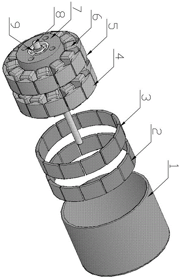
[0025] Embodiment 1: Two-phase 12-pole outer rotor permanent magnet stepper motor. attached figure 1 , 2 , 3, and 4 respectively give the structure and operation mode of the two-phase 12-pole outer rotor permanent magnet stepper motor. figure 1 Structural diagram of two-phase 12-pole outer rotor permanent magnet stepper motor, including sub-stator 4 and sub-stator 5 made of ferrosilicon sheet, enameled wire coil 6, aluminum stator seat 7, shaft 8 made of stainless steel, bearing 9 and other parts The overall inner stator of the two-phase 12-pole outer rotor permanent magnet stepper motor is formed, and the pole teeth of the two sub-stators are aligned; the rotor provides magnets 2 and 3, which are composed of 2x12 pieces of magnets, and the poles of adjacent magnets On the contrary, it is evenly distributed on the ring surface, there is a gap between each magnet ring, the installation angle difference of the two magnet rings is 15 degrees, and all the gaps in one magnet ring...
Embodiment 2
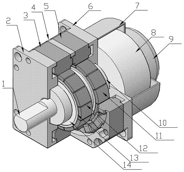
[0029] Embodiment 2: Two-phase 12-pole inner rotor stepping servo motor. As shown in the figure, it includes sub-stators 3 and 5 made of magnetic materials, two rotors 13, magnetic steel rings 11 and 12 made of permanent magnetic materials, shaft 1 made of non-magnetic materials, end covers 2 and 6, and stator spacers. Plate 4, rotor seat 14, and two bearings 10, brake housing 7, brake 8, and angle sensor 9. There are 12 pole teeth on each stator, the pole teeth are wound with coils, and the winding directions of adjacent pole teeth are opposite. There is a stator partition between the two stators to isolate the two stator magnetic circuits. The two stator teeth are Aligned; 12 pieces of magnetic steel are evenly distributed on each sub-rotor, and the polarity of adjacent magnetic steel is opposite. On the seat, the center plane of the sub-rotor perpendicular to the shaft overlaps with the center plane of the respective stator perpendicular to the shaft; the rotor seat is ins...
Embodiment 3
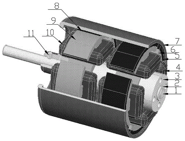
[0031] Embodiment 3: Two-phase four-pole non-dead point external rotor brushless motor. As shown in the figure, 1 shaft 1 made of non-magnetic material, 2 shaft sleeves 2, a stator seat 3, 2 coils 4 and 10, 2 Hall elements 5, 2 4-pole stators 6 and 9, and a rotor Seat 7, 8 pieces of magnetic steel 8, 1 axle pin 11 constitute; Two rotors are mutually staggered 30-60 degree; Stator is aligned. Due to the misalignment of the dead points, at any time, a sub-motor can start normally, and can change direction during operation. This embodiment is suitable for economical operation, no dead point, quick start, low noise, high energy efficiency, simple manufacture, and low cost. auto parts etc.
PUM
 Abstract
Description
Claims
Application Information
 - R&D
- Intellectual Property
- Life Sciences
- Materials
- Tech Scout
- Unparalleled Data Quality
- Higher Quality Content
- 60% Fewer Hallucinations
Browse by: Latest US Patents, China's latest patents, Technical Efficacy Thesaurus, Application Domain, Technology Topic, Popular Technical Reports.
© 2025 PatSnap. All rights reserved.Legal|Privacy policy|Modern Slavery Act Transparency Statement|Sitemap|About US| Contact US: help@patsnap.com


