Operation Method of Discrete Stepping Control for Permanent Magnet Brushless DC Motor

A permanent magnet brushless DC, operating method technology, applied in motor generator control, electronic commutation motor control, control system and other directions, can solve the problems of difficult positioning and low positioning accuracy, achieve accurate positioning and improve position resolution , the effect of high-precision positioning control

Active Publication Date: 2017-02-22
HEBEI UNIV OF TECH
View PDF4 Cites 0 Cited by
  • Summary
  • Abstract
  • Description
  • Claims
  • Application Information

AI Technical Summary

Problems solved by technology

The existing permanent magnet brushless DC motor uses Hall elements to detect the rotor position, adopts two-two conduction mode, and the commutation angle is 60°, which is equivalent to stepping the stator magnetic field every 60°. It is difficult to perform accurate positioning, even if two-three The conduction method reduces the commutation angle by half, but the positioning accuracy is still not high

Method used


Image

  • Operation Method of Discrete Stepping Control for Permanent Magnet Brushless DC Motor
  • Operation Method of Discrete Stepping Control for Permanent Magnet Brushless DC Motor
  • Operation Method of Discrete Stepping Control for Permanent Magnet Brushless DC Motor

Examples


Embodiment 1

[0054] A. The device and operation used in the operation method:

[0055] The device used in the operation method of the discrete step control of the permanent magnet brushless DC motor includes a DSP control module 1, a power circuit 2, a permanent magnet brushless DC motor 3, an encoder position detection module 4 and an input power supply module 5, wherein the input power supply Module 5 supplies power for DSP control module 1, power circuit 2 and encoder position detection module 4, DSP control module 1, power circuit 2, permanent magnet brushless DC motor 3 and encoder position detection module 4 are connected with wires in sequence, and the encoding The encoder position detection module 4 is connected to the DSP control module 1 with wires; first, the input power supply module 5 supplies power to the DSP control module 1, the power circuit 2 and the encoder position detection module 4, and then the encoder position detection module 4 detects the permanent magnet The init...

Embodiment 2

[0072] In this embodiment, within a cycle period, the three-phase current is discrete according to the operation method of the present invention, and the number of cycles is b H = 24, when the current vector is 1 step ahead, the motor is controlled to run step by step, I m =5A, give the current vector one step forward every 0.1s, observe the motor A phase current waveform (current-time curve) (see Figure 6 (1)), the rotor stepping operation position graph (position-time curve) (see Figure 6 (2)) and the output electromagnetic torque figure (electromagnetic torque-time curve) (referring to Fig. 6 (3)), as can be seen from the result, the present embodiment uses the B operation method according to embodiment 1, phase current ( Figure 6 (1)) presents a stepped trapezoidal wave, and the initial electromagnetic torque of each step (see Figure 6 (3)) presents periodic fluctuations due to position changes, and the rotor operates under the action of the electromagnetic torque. When t...

Embodiment 3

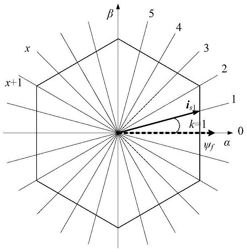
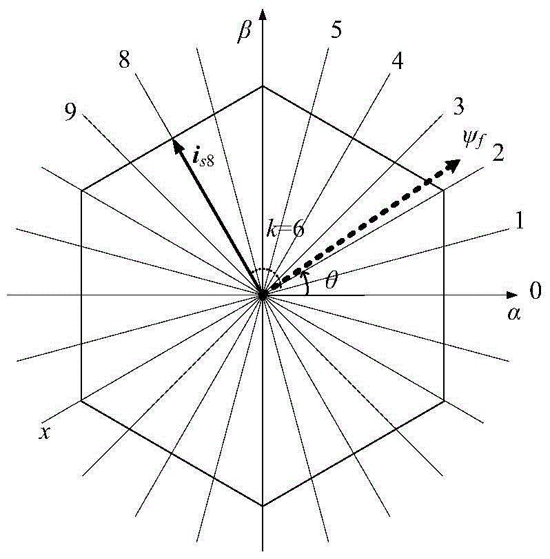
[0074] In this embodiment, within a cycle period, the three-phase current is discrete according to the above-mentioned discrete step control, and the number of cycles is b H =24, setting motor mechanical speed 125r / min, the maximum current vector amplitude is I m =5A, adopt the advance step number k=6 to control, calculate the corresponding current vector according to the B operation method of embodiment 1, calculate and observe the A phase current-time curve obtained under the constant speed running state of the motor (referring to Fig. 7 ( 1)), the rotor step running position-time curve (see Figure 7 (2)) and the output electromagnetic torque-time curve (see Figure 7 (3)), the electromagnetic torque has certain regular fluctuations, but the up and down fluctuations It does not exceed 0.5Nm, and its change process is gentle. The electromagnetic torque provided provides a relatively stable load capacity in practice, can maintain the smooth operation of the motor, and is easy t...


PUM


Abstract

The invention discloses an operation method for stepping dispersion control on a permanent magnet brushless direct current motor, and relates to a motor control technology. A device used in the method comprises a DSP (digital signal processing) control module, a power circuit, the permanent magnet brushless direct current motor, an encoder position detection module and an input power module. For the common three-phase permanent magnet brushless direct current motor, a stator current vector synthesized by three-phase current is dispersed and subdivided, and a dispersion positioning position in a space is obtained according to a certain cyclic number of beats, so that positioning control on the motor can be realized by controlling the space position of a stator magnetic field, and the positioning precision of the motor is improved; furthermore, the stator current vector synthesized by the three-phase current is dispersed at an electric angle space position according to a certain cyclic number of beats so as to obtain a dispersed current vector for controlling operation of the motor; by increase of the cyclic number of beats, a smaller stepping angle can be obtained, and the position resolution is improved; therefore, the positioning precision of the permanent magnet brushless direct current motor can be improved under the condition of guaranteeing the loading capacity.

Description

technical field [0001] The technical proposal of the invention relates to a motor control technology, in particular to an operation method of discrete step control of a permanent magnet brushless DC motor. Background technique [0002] A permanent magnet brushless DC motor is composed of a stator winding and a permanent magnet rotor without a commutator, and its control characteristics are similar to a brushed DC motor. Due to its advantages of large torque, high efficiency, high speed, simple control and easy maintenance, and with the development of power electronics technology, permanent magnet materials, digital electronics technology and new control theory, permanent magnet brushless DC motors are used in high The field of performance servo drives shows broad application prospects. The existing permanent magnet brushless DC motor uses Hall elements to detect the rotor position, adopts two-two conduction mode, and the commutation angle is 60°, which is equivalent to step...

Claims


Application Information

Patent Timeline
Patent Type & Authority Patents(China)
IPC IPC(8): H02P21/12
Inventor 孙鹤旭董砚荆锴郑易雷兆明崔向宇崔彦召梁发金
Owner HEBEI UNIV OF TECH
Why Eureka
Try Eureka