A Method for Observing Flux Linkage of Asynchronous Motor Based on Sliding Mode Observer

A sliding mode observer, asynchronous motor technology, applied in the control of generators, motor generator control, electronic commutation motor control and other directions, can solve the problems affecting the accuracy of flux linkage observation, discontinuous control items, complex system design, etc.

Active Publication Date: 2018-05-29
HEFEI UNIV OF TECH
View PDF8 Cites 0 Cited by
  • Summary
  • Abstract
  • Description
  • Claims
  • Application Information

AI Technical Summary

Problems solved by technology

Among them, the scheme of obtaining the rotor flux linkage based on the back electromotive force has good rotor resistance robustness, but the first-order current sliding mode observer needs to filter the control items to obtain the back electromotive force, which affects the accuracy of the flux linkage observation , and the inductance parameter robustness is poor
In response to these problems, some scholars have carried out further research on this scheme. The main methods are: 1. Design a continuous sliding mode observer to solve the problem of discontinuity in the control item, but the calculation of the rotor flux linkage needs to pass the integral of the back electromotive force Obtained, it is easy to generate DC bias, and the robustness of the inductance parameters is still poor; 2. Design two current sliding mode observers, and use the special relationship between the two control items to further design the flux linkage observer, which not only overcomes the integral problem, and further improved the robustness of the system parameters, but the system design is more complex and engineering application is more difficult

Method used


Image

  • A Method for Observing Flux Linkage of Asynchronous Motor Based on Sliding Mode Observer
  • A Method for Observing Flux Linkage of Asynchronous Motor Based on Sliding Mode Observer
  • A Method for Observing Flux Linkage of Asynchronous Motor Based on Sliding Mode Observer

Examples


Embodiment Construction

[0070] The present invention will be further described below with reference to the drawings and embodiments.

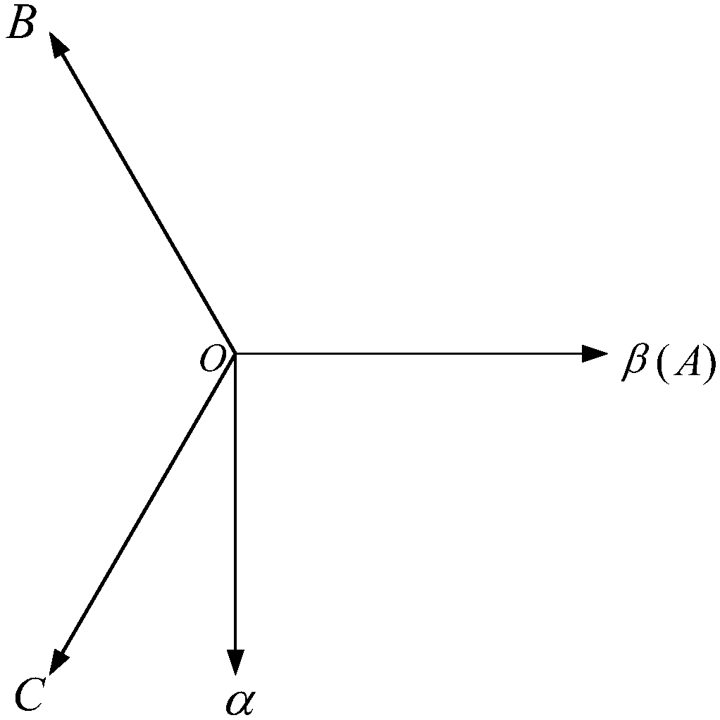
[0071] In the signal acquisition part, the stator voltage vector V and the stator current vector i are obtained by sampling the stator line voltage U ab , Stator line voltage U cb , Stator A phase current i A , Stator B phase current i B , Stator C phase current i C , And obtained by transforming the three-phase stationary coordinate system to the two-phase stationary coordinate system, the actual rotor electrical angular velocity ω r It is obtained by photoelectric rotary encoder. This embodiment proceeds as follows:

[0072] Step 1. Collect the stator voltage vector V, stator current vector i, and rotor electrical angular velocity ω of the asynchronous motor in the static coordinate system αβ r ;

[0073] Step 2. Establish the state space expression of the asynchronous motor in the static coordinate system αβ as:

[0074]

[0075] In formula (1), e is the back-EMF vector, ...


PUM


Abstract

The invention discloses a sliding-mode observer based flux linkage observation method of an asynchronous motor. The flux linkage observation method is characterized by comprising the following steps of acquiring a continuous counter electromotive force e by Omega<r> through a high-order current sliding-mode observer according to a stator voltage vector v, a stator current vector i and a rotor electric angular speed, which are obtained through acquisition and operation, of the motor under a two-phase static coordinate AlphaBeta; building a state space expression of the asynchronous motor according to a relation between the counter electromotive force and rotor flux linkage; and building a flux linkage sliding mode observer according to the space expression. By the flux linkage observation method, the integral problem in flux linkage observation is solved, and relatively high robustness is generated for parameters such as rotor resistance, excitation inductance, rotor inductance and stator inductance; and meanwhile, the observer is simple in design, and engineering implementation is easy.

Description

Technical field [0001] The invention relates to a flux linkage observer, in particular to an asynchronous motor rotor flux linkage sliding mode observer. Background technique [0002] With the gradual exhaustion of fossil energy and the increasingly serious problems caused by the greenhouse effect, the development and utilization of new energy has gradually become a research focus. In recent years, as an energy-saving and environmentally friendly means of transportation, electric vehicles have received great attention from the government. Asynchronous motors (IM) have the most extensive application prospects in the field of electric vehicles due to their good stability, simple structure, maintenance-free, and wide speed range. [0003] The IM speed control system in industrial applications is generally composed of a current loop and a speed loop. The output of the speed loop is set as the current loop, so that it has better tracking performance for the speed. However, in the elec...

Claims


Application Information

Patent Timeline
Patent Type & Authority Patents(China)
IPC IPC(8): H02P21/13
CPCH02P21/13
Inventor 杨淑英丁大尉李曦张兴谢震
Owner HEFEI UNIV OF TECH
Why Eureka
Try Eureka