
Bionic mechanical arm

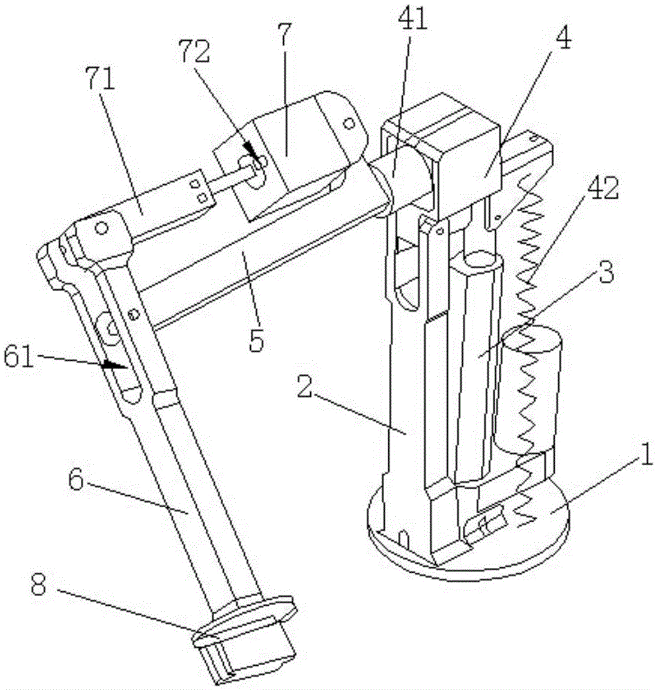
A bionic machine and arm lever technology, applied in the field of bionic robotic arms, can solve the problems of inflexible activities, increased manufacturing costs, limited range of activities, etc., and meet the requirements of reducing production costs, reducing force, reducing materials and processing technology. Effect

Active Publication Date: 2016-06-01
常州墨狄机器人科技有限公司
View PDF17 Cites 16 Cited by
  • Summary
  • Abstract
  • Description
  • Claims
  • Application Information

AI Technical Summary

Problems solved by technology

The manipulator controls the lifting through the lifting cylinder of the fuselage, rotates around the central axis of the lifting cylinder through the rotary cylinder of the fuselage, and controls the horizontal movement through the telescopic cylinder of the arm. It is also not flexible enough. It may be sufficient as an industrial manipulator. If it is used in other fields, it needs further improvement.
[0005] For example, the application number is 201510607815.0, which is an invention patent publication titled "a multi-joint bionic manipulator", which discloses a multi-joint bionic manipulator, including a base, shoulder joints, elbow joints, wrist joints and The composition is characterized in that the shoulder joint is installed in the base; the elbow joint is installed at the end of the shoulder joint through the joint pair; the wrist joint is arranged at the end of the elbow joint through the joint pair; the joint pair is installed at the end of the wrist joint and is installed on the wrist Rotation and swing are realized under the drive of the rotation motor and swing motor in the joint; the base, shoulder joint, elbow joint and wrist joint are connected in series to form a bionic robotic arm, which imitates the human arm with multiple joints, flexible and large range of motion, but its The motors driving each joint are directly installed on the joint, which requires a complex deceleration mechanism to achieve a high end load and a closed-loop control circuit to precisely control the angle of each joint, and also increase the force on the end to improve the multi-material And the requirements of the manufacturing process, thereby increasing the manufacturing cost, so its structure also needs to be further improved

Method used


Image

  • Bionic mechanical arm
  • Bionic mechanical arm
  • Bionic mechanical arm

Examples


Embodiment Construction

[0025] In order to make the purpose and technical solutions of the embodiments of the present invention more clear, the technical solutions of the embodiments of the present invention will be clearly and completely described below in conjunction with the drawings of the embodiments of the present invention. Apparently, the described embodiments are some, not all, embodiments of the present invention. Based on the described embodiments of the present invention, all other embodiments obtained by persons of ordinary skill in the art without creative efforts shall fall within the protection scope of the present invention.

[0026] The present invention is described in further detail now in conjunction with accompanying drawing. These drawings are all simplified schematic diagrams, which only illustrate the basic structure of the present invention in a schematic manner, so they only show the configurations related to the present invention.

[0027] A bionic mechanical arm, compris...


PUM


Abstract

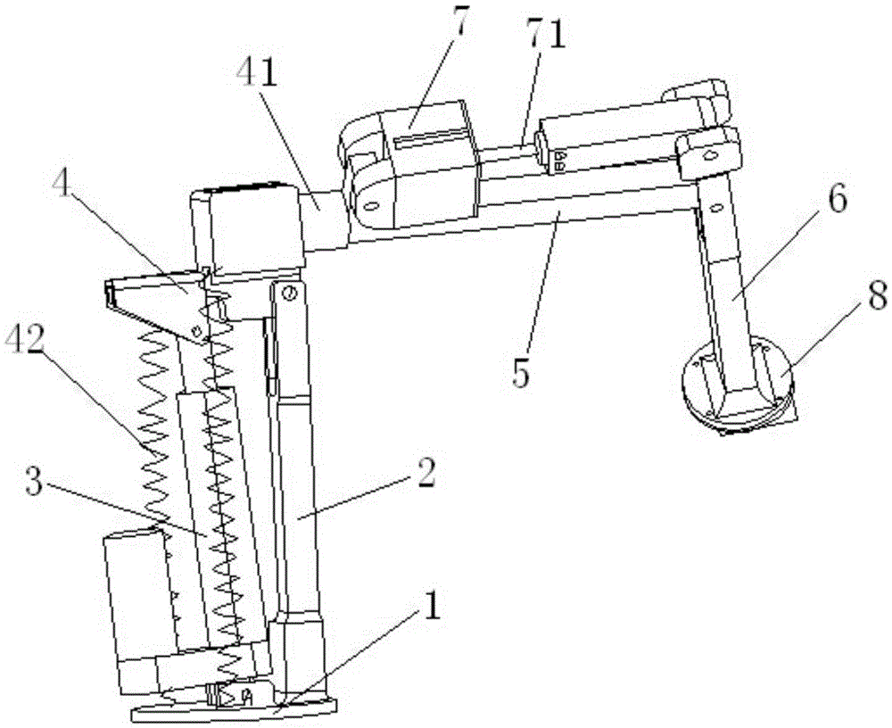
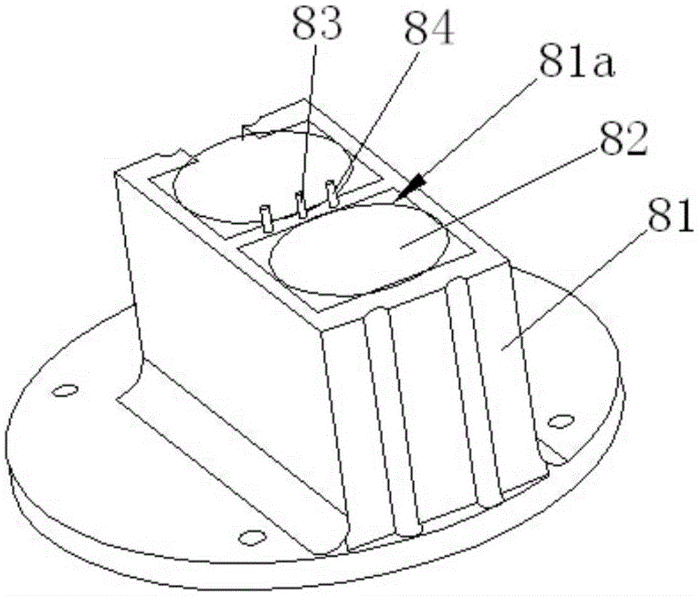
The invention discloses a bionic mechanical arm. The bionic mechanical arm comprises a base. A base support and a linear movement control piece are fixed to the base. A big arm base is hinged to the upper end of the base support. The big arm base is connected with the linear movement control piece and also connected with one end of a big arm rod. The other end of the big arm rod is hinged to a small arm rod. A lead screw stepping motor is arranged at the end, away from the small arm rod, of the big arm rod. A telescopic rod on the lead screw stepping motor is hinged to one end of the small arm rod. A paw fixing piece is arranged at the other end of the small arm rod. The bionic mechanical arm has the advantages that the structure is simple and reasonable; a control piece is arranged in the position away from a hinge point by fully utilizing the level principle, so that the effect of saving labor is achieved, and the weight of the mechanical arm is reduced; in addition, the stress of the tail end is reduced, so that the requirements for materials and machining techniques are lowered, and the production cost is effectively reduced.

Description

technical field [0001] The invention relates to the technical field of robots, in particular to a bionic mechanical arm. Background technique [0002] With the continuous development of science and technology and the continuous increase of labor costs, more and more robots or mechanical arms are used in industrial production to complete production. The wide use of robots or mechanical arms in industrial production can not only improve the degree of automation and improve production efficiency, Moreover, it can reduce the working intensity of laborers and avoid work in some dangerous environments. For example, in harsh environments such as high temperature, high pressure, low temperature, low pressure, dust, explosive, toxic gas and radioactivity, robots can replace laborers to complete the work. Protect the safety of workers well. [0003] In addition, some born disabled people and some disabled people whose limbs have been amputated due to accidents will install prosthetic...

Claims


Application Information

Patent Timeline
IPC IPC(8): B25J9/12B25J19/00
CPCB25J9/12B25J19/0016
Inventor 汤志强
Owner 常州墨狄机器人科技有限公司
Learn More