Mechanical arm

A technology of mechanical arms and mechanical grippers, applied in the field of mechanical arms, can solve the problems of inability to meet precision requirements, position control and easy to get stuck, and reduce detection efficiency, so as to achieve the effects of convenient control, precise positioning, and improved detection efficiency

Inactive Publication Date: 2016-06-01
NANJING NORMAN BIOLOGICAL TECH
View PDF8 Cites 9 Cited by
  • Summary
  • Abstract
  • Description
  • Claims
  • Application Information

AI Technical Summary

Problems solved by technology

[0002] In the process of pharmaceutical production, there are two main ways to grasp cuvettes. One is to manually grasp the operation, but the production efficiency is low and error-prone; the other is to use machinery to automatically grasp, but this type of equipment mainly The entire manipulator is driven by the ordinary motor-driven chain. The positioning error of the device is large and the operation is not stable, the relia

Method used


Image

  • Mechanical arm
  • Mechanical arm
  • Mechanical arm

Examples


Embodiment

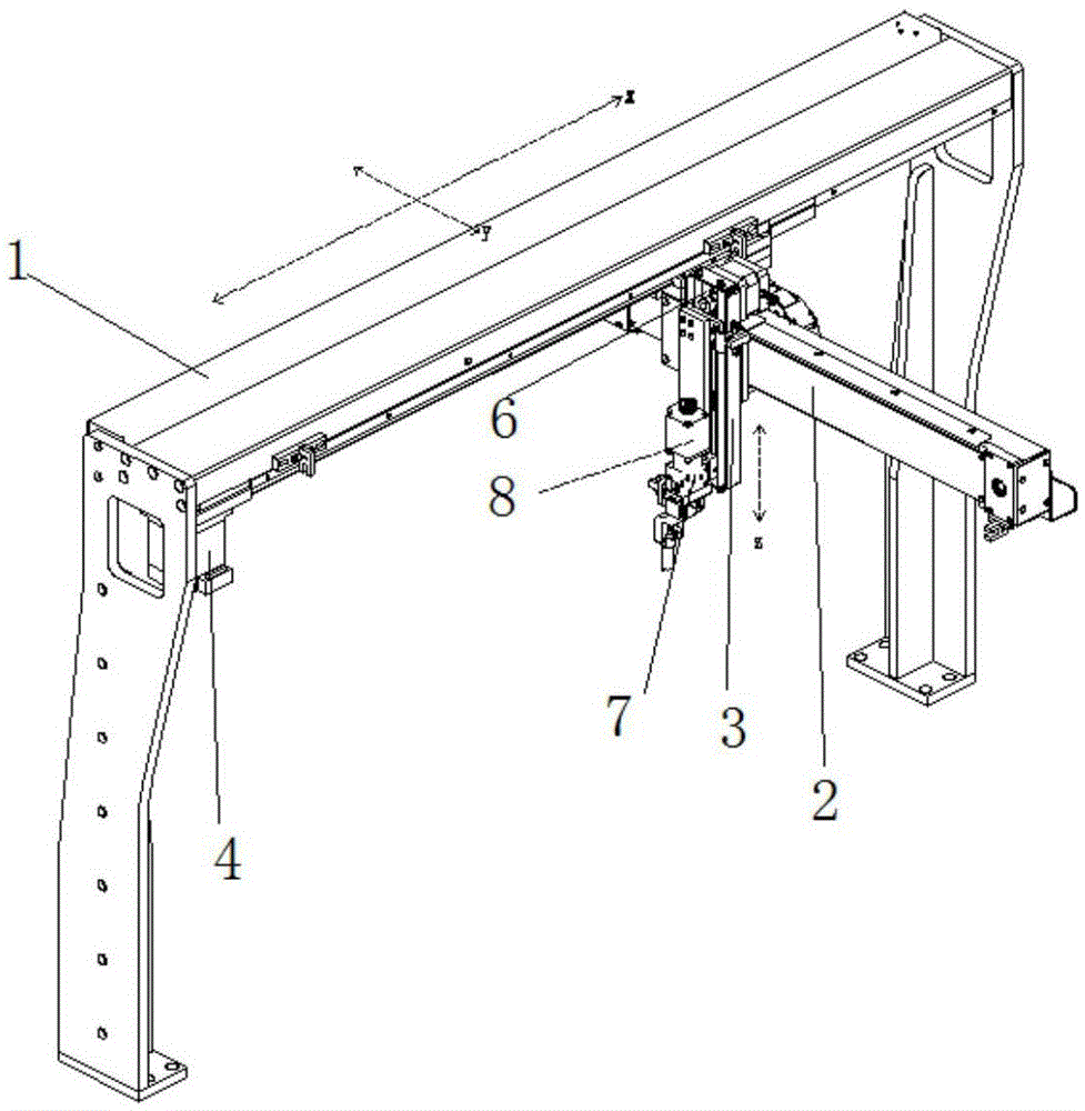
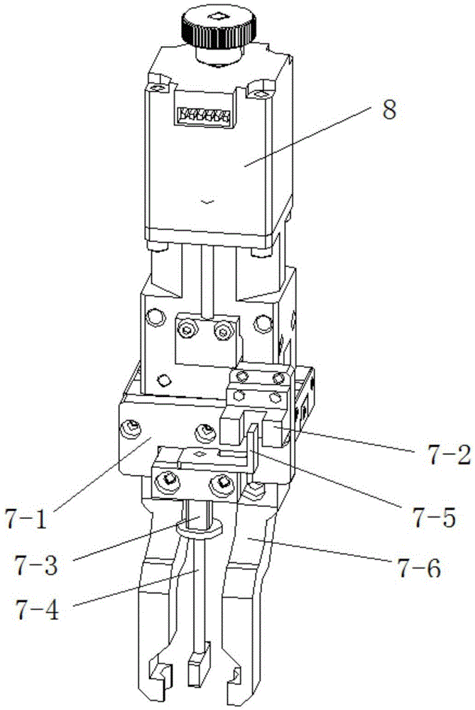
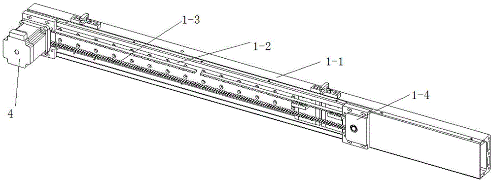
[0036] like Figure 1 to Figure 6 As shown, the mechanical arm includes X-axis guide rail assembly 1, Y-axis guide rail assembly 2, Z-axis guide rail assembly 3, X-axis motor 4, Y-axis motor 5, Z-axis motor 6, mechanical gripper 7 and mechanical gripper motor 8, The X-axis rail assembly 1 is connected to the X-axis motor 4, the Y-axis rail assembly 2 is connected to the Y-axis motor 5, the Z-axis rail assembly 3 is connected to the Z-axis motor 6, and the mechanical grip The hand 7 is connected to the mechanical gripper motor 8; the Y-axis guide rail assembly 2 is arranged on the X-axis guide rail assembly 1, the Z-axis guide rail assembly 3 is arranged on the Y-axis guide rail assembly 2, and the mechanical gripper 7 is arranged on the Z-axis guide rail assembly 3; the mechanical gripper 7 includes a gripper 7-6 and a detection device, and the detection device is arranged above the gripper 7-6.

[0037] The detection device includes a fixed block 7-1, an optocoupler 7-2, a s...


PUM


Abstract

The invention discloses a mechanical arm, and belongs to the field of chemiluminescence measurement. The mechanical arm comprises an X-axis guide rail assembly, a Y-axis guide rail assembly, a Z-axis guide rail assembly, an X-axis motor, a Y-axis motor, a Z-axis motor, a mechanical gripper and a mechanical gripper motor. The X-axis guide rail assembly is connected with the X-axis motor. The Y-axis guide rail assembly is connected with the Y-axis motor. The Z-axis guide rail assembly is connected with the Z-axis motor. The mechanical gripper is connected with the mechanical gripper motor. The Y-axis guide rail assembly is arranged on the X-axis guide rail assembly. The Z-axis guide rail assembly is arranged on the Y-axis guide rail assembly. The mechanical gripper is arranged on the Z-axis guide rail assembly. The mechanical gripper comprises a clamping jaw and a detection device, and the detection device is arranged above the clamping jaw. The mechanical arm can run in three-dimensional space flexibly and stably, and can detect whether a reaction cup is clamped or not.

Description

technical field [0001] The invention relates to the field of chemiluminescence assay, in particular to a mechanical arm. Background technique [0002] In the process of pharmaceutical production, there are two main ways to grasp cuvettes. One is to manually grasp the operation, but the production efficiency is low and error-prone; the other is to use machinery to automatically grasp, but this type of equipment mainly The entire manipulator is driven by a chain driven by an ordinary motor. The positioning error of this device is large, the operation is not stable, the reliability is poor, and the position control is also easy to get stuck. [0003] In addition, the mechanical gripper in the prior art has no detection device. When the gripper grabs the cuvette, it cannot sense whether the cuvette is clamped, which will easily cause the phenomenon of empty claws. Without the operation of manual monitoring equipment, reduce detection efficiency. Contents of the invention [...

Claims


Application Information

Patent Timeline
IPC IPC(8): B25J19/02B25J15/08
CPCB25J19/02B25J15/08
Inventor 何仕钊
Owner NANJING NORMAN BIOLOGICAL TECH
Why Eureka
Try Eureka