
Extruding machine

An extruder and barrel technology, applied in the field of extruders, can solve the problems of affecting the quality of finished products, easy to block the internal pipes of the extruder, and high energy consumption, so as to increase the processing speed and processing quality, and enhance the plasticizing shear. The effect of cutting effect and improving product quality

Inactive Publication Date: 2016-06-01
SHENGZHOU YIHAI MOTOR PARTS FACTORY
View PDF0 Cites 24 Cited by
  • Summary
  • Abstract
  • Description
  • Claims
  • Application Information

AI Technical Summary

Problems solved by technology

After the material enters the extruder, it is very easy to block the internal pipe of the extruder, which will easily cause the blockage of the whole equipment and affect the production; the material loading needs to be lifted up manually, which is extremely inconvenient, time-consuming and laborious. Screw extruder The inner center position is mainly used to complete the functions of mixture transmission, plasticization, molding, etc. The existing screw extruder has pressure but no plasticizing shear mixing effect, and has no stirring force for the mixing and mixing of various raw materials. High consumption and low output; water vapor and small molecule excrement produced during plastic processing cannot be discharged in time, which will not only affect the quality of the finished product, but also release toxic gas after the plastic is extruded from the machine head, endangering the working environment and worker health

Method used


Image

  • Extruding machine
  • Extruding machine
  • Extruding machine

Examples


Embodiment Construction

[0017] The preferred embodiments of the present invention will be described in further detail in conjunction with the accompanying drawings.

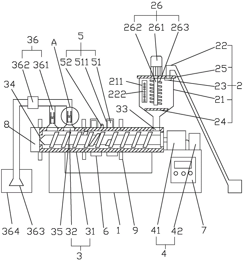
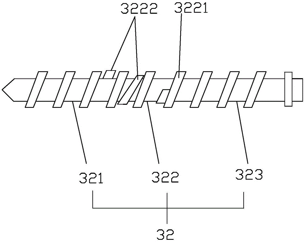
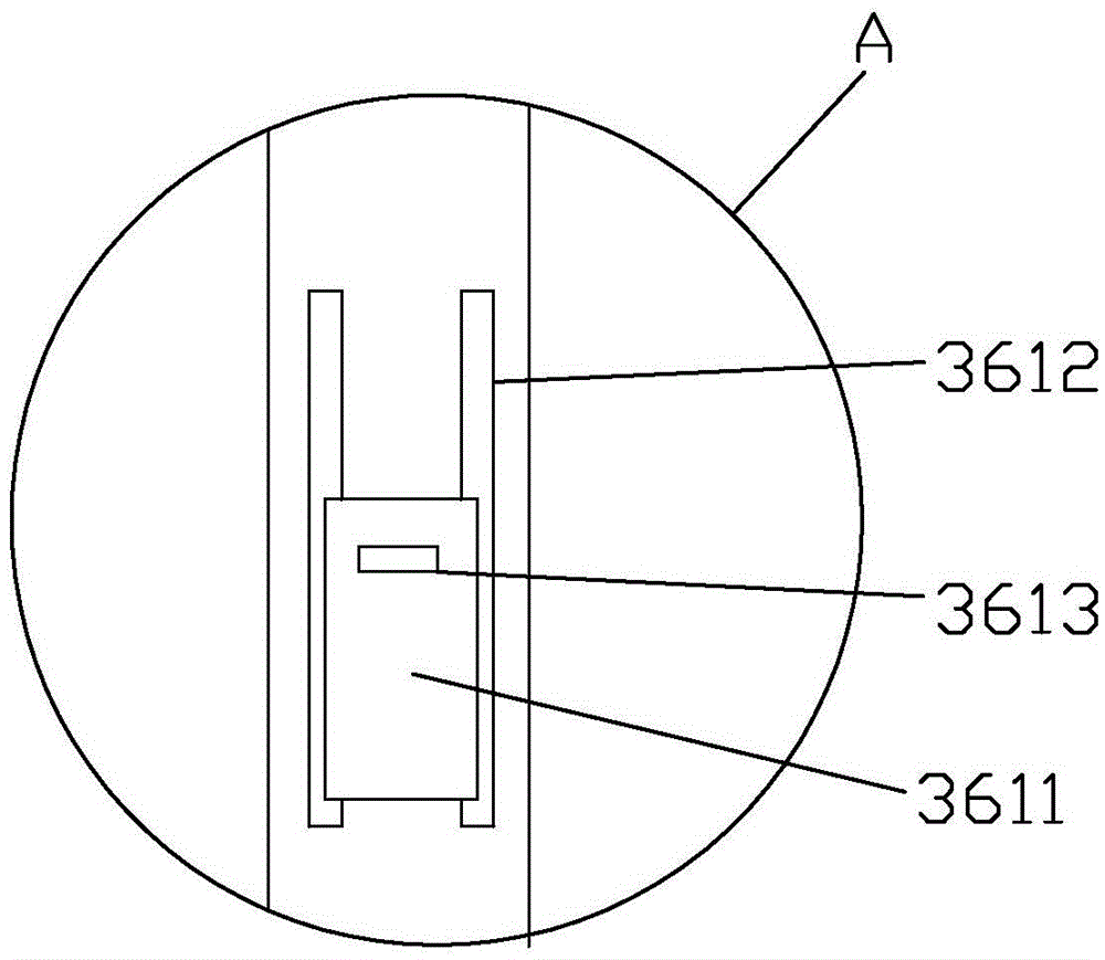
[0018] Such as Figure 1-3 Described a kind of extruder comprises machine base 1, feeding system 2, extruding system 3, transmission system 4, heating system 5, cooling system 6, electric control system 7 and machine head 8, and described feeding system 2 includes a hopper 21 and a feeding screw 22, the hopper 21 adopts a conical hopper 21, a transparent window 211 is provided on the outside of the hopper 21, and a scale line 222 is provided on the transparent window 211, and the Material balance, you can add materials in time. The feeding screw 22 is connected to the hopper 21, which can automatically feed materials to save manpower. The connection between the feeding screw 22 and the hopper 21 is provided with a filter screen 23 for filtering impurities, and the bottom of the hopper 21 is provided with an opening and closing door 24....


PUM


Abstract

The invention mainly discloses an extruding machine. According to the technical scheme, the extruding machine comprises a machine base, a feeding system, an extruding system, a transmission system, a heating system, a cooling system, an electric control system and a machine head. The feeding system comprises a hopper and a material conveying screw. A filtering net is arranged at the connecting position of the material conveying screw and the hopper. An opening and closing door is arranged at the bottom of the hopper. The extruding system comprises a machine cylinder and a separated type screw arranged in the machine cylinder. A feeding port, a discharging port and a smoke outlet are formed in the machine cylinder. An exhaust system is arranged at the position of the smoke outlet. The heating system and the cooling system are connected to the outer side of the machine cylinder. The material conveying screw can convey materials to the hopper automatically so that labor force can be saved; impurities can be filtered out through the filtering net; the opening and closing door is arranged at the bottom of the hopper so that feeding can be stopped and the feeding amount can be adjusted; a stirrer is arranged in the hopper for stirring the materials, and accumulating and blocking at the position of the feeding port of the machine cylinder are avoided; and the exhaust system can remove pollutants such as sulfur dioxide smoke and lampblack through purification, and therefore environment pollution in the production process is effectively avoided.

Description

technical field [0001] The invention relates to the field of manufacturing technology, in particular to an extruder. Background technique [0002] Extruders are widely used in the production of plastics, rubber and other products, and have become one of the most widely used models in the plastics processing industry. After the material enters the extruder, it is very easy to block the internal pipe of the extruder, which will easily cause the blockage of the whole equipment and affect the production; the material loading needs to be lifted up manually, which is extremely inconvenient, time-consuming and laborious. Screw extruder The inner center position is mainly used to complete the functions of mixture transmission, plasticization, molding, etc. The existing screw extruder has pressure but no plasticizing shear mixing effect, and has no stirring force for the mixing and mixing of various raw materials. High consumption and low output; water vapor and small molecule excre...

Claims


Application Information

Patent Timeline
Patent Type & Authority Applications(China)
IPC IPC(8): B29C47/00B29C47/10B29C47/38B29C47/62B29C47/76B07B1/04B29B7/14B29C48/395B29C48/76
CPCB07B1/04B29B7/14B29C48/00B29C48/285B29C48/287B29C48/397B29C48/65B29C48/763B29C48/767
Inventor 陈意
Owner SHENGZHOU YIHAI MOTOR PARTS FACTORY
Learn More