
High-precision galvanometer error self-correcting device and high-precision galvanometer error self-correcting method based on machine vision

A machine vision and self-calibration technology, applied in printing and other directions, can solve problems such as deformation of marking graphics, achieve the effects of avoiding distortion, improving accuracy and reliability, and avoiding deformation of marking graphics

Active Publication Date: 2016-06-01
HANS LASER TECH IND GRP CO LTD +1
View PDF5 Cites 26 Cited by
  • Summary
  • Abstract
  • Description
  • Claims
  • Application Information

AI Technical Summary

Problems solved by technology

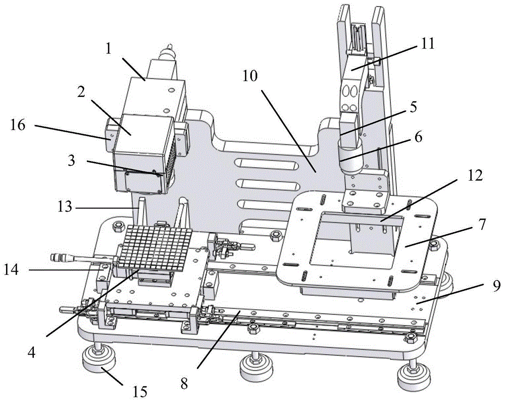
[0003] The purpose of the present invention is to address the technical problems existing in the prior art, to provide a high-precision galvanometer error self-correction device and method based on machine vision, which can solve the problems caused by linear distortion and nonlinear distortion in the marking process. The problem of deformation of marking graphics

Method used


Image

  • High-precision galvanometer error self-correcting device and high-precision galvanometer error self-correcting method based on machine vision
  • High-precision galvanometer error self-correcting device and high-precision galvanometer error self-correcting method based on machine vision
  • High-precision galvanometer error self-correcting device and high-precision galvanometer error self-correcting method based on machine vision

Examples


Embodiment Construction

[0030] In order to facilitate understanding of the present invention, the present invention will be described more fully hereinafter with reference to the related drawings. Preferred embodiments of the invention are shown in the accompanying drawings. However, the present invention may be embodied in many different forms and is not limited to the embodiments described herein. Rather, these embodiments are provided so that a thorough and complete understanding of the present disclosure is provided.

[0031] Unless otherwise defined, all technical and scientific terms used herein have the same meaning as commonly understood by one of ordinary skill in the art to which this invention belongs. The terms used herein in the description of the present invention are for the purpose of describing specific embodiments only, and are not intended to limit the present invention.

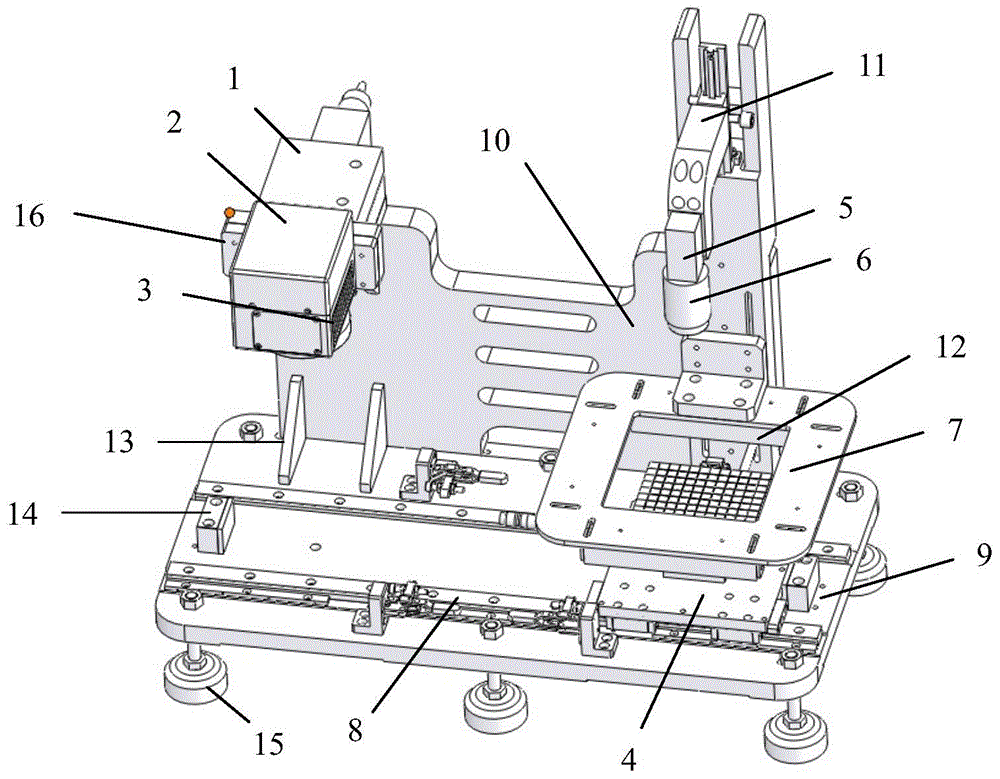
[0032] see figure 1 As shown in the figure, the present invention provides a high-precision galvanometer er...


PUM


Abstract

The invention discloses a high-precision galvanometer error self-correcting device and a high-precision galvanometer error self-correcting method based on machine vision. The self-correcting device comprises a laser, a marking square head, a focusing lens, an XY-axis movement platform, a camera, an X-axis movement guiderail and a mounting base. The mounting base is provided with an X-axis movement guiderail and a vertical plate. The XY-axis movement platform is mounted on the X-axis movement guiderail. The laser and the camera are mounted on the side surface of the mounting base. The camera is connected with an external image processor. The marking square head is mounted on the side surface of the laser. The focusing lens is mounted on the lower end surface of the marking square head. According to the self-correcting method of the invention, a two-dimensional correction table in practical application of laser marking is obtained through a vision method, namely utilizing the camera and the lens; a laser marking device is corrected by means of the vision method; a unique correction table can be generated for each laser marking device, thereby improving precision and reliability in laser marking and preventing linear distortion and nonlinear distortion in the marking process.

Description

technical field [0001] The invention relates to the technical field of opto-mechanical integration, and more particularly, to a high-precision galvanometer error self-correction device and method based on machine vision. Background technique [0002] In modern society, the application scope of laser scanning technology is getting wider and wider, and its application industries involve optoelectronic medical treatment, laser processing, laser cutting, laser welding, etc. In the application of various laser scanning technologies, it is required that the laser beam can be accurately focused on any position on the field of view, and the movement of the light spot is performed according to a certain relationship. Among various laser scanning technologies, galvanometer scanning is a widely used scanning method. It has the advantages of high speed and high positioning accuracy. However, in the actual use process, there is an inherent geometric distortion error of the scanning fie...

Claims


Application Information

Patent Timeline
Patent Type & Authority Applications(China)
IPC IPC(8): B41J2/435
Inventor 闫静李玉廷王光能舒远丁兵李文龙高云峰
Owner HANS LASER TECH IND GRP CO LTD
Learn More