Hollow-shaft ram-rotor based on shock wave compression technology

A compression technology, ram compression technology, applied to parts of pumping devices for elastic fluids, non-variable pumps, machines/engines, etc., can solve the problem that the power-to-weight ratio of gas turbines has no essential influence, and the volume and weight of the compression system Larger, lower total compression efficiency and other issues, to achieve the effect of light weight, high compression efficiency and high boost ratio

Inactive Publication Date: 2016-06-01
DALIAN MARITIME UNIVERSITY
View PDF0 Cites 4 Cited by
  • Summary
  • Abstract
  • Description
  • Claims
  • Application Information

AI Technical Summary

Problems solved by technology

Axial flow compression has high single-stage compression efficiency, wide application, and mature technology, but its single-stage pressure ratio is low, multi-stage compression is required to achieve high pressure ratio, the volume and weight of the compression system are large, and the total compression efficiency is reduced; centrifugal compression single-stage compression Relatively high, relatively stable performance, but its efficiency is low
The above two airflow compression methods can also be used in combination, but it has no essential effect on improving the power-to-weight ratio of the gas turbine

Method used


Image

  • Hollow-shaft ram-rotor based on shock wave compression technology
  • Hollow-shaft ram-rotor based on shock wave compression technology
  • Hollow-shaft ram-rotor based on shock wave compression technology

Examples


Embodiment Construction

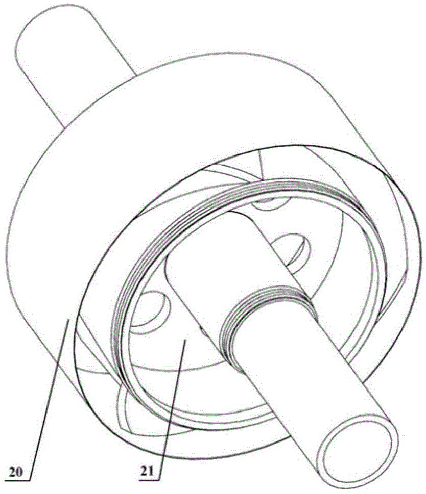
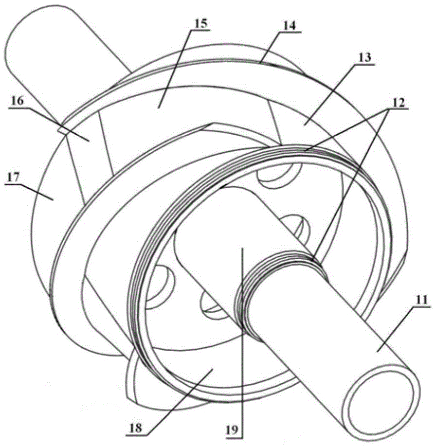
[0027] Such as figure 1 with figure 2 The shown hollow shaft rotary stamping compression rotor based on shock wave compression technology includes: a hollow shaft 11, a wheel assembly that rotates synchronously with the hollow shaft 11, and an outer casing 20 that is placed outside the wheel assembly;

[0028] Wherein, the outer wall surface of the outer edge 13 of the roulette assembly is evenly distributed with a plurality of spiral partitions 14, and the installation angle of each spiral partition 14 is the same;

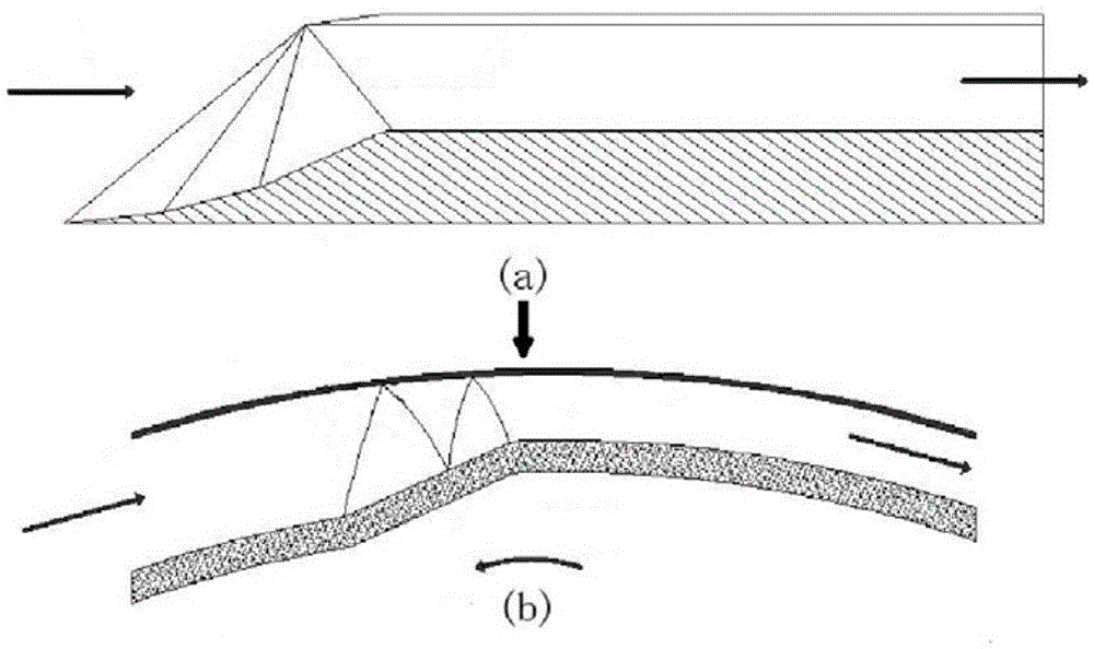
[0029] The gap between every two adjacent spiral partitions 14 forms an air intake channel, and each air intake channel is provided with an airflow compression section 15, a throat isolation section 16 and a triangular outlet extension section 17 in sequence from the inlet end to the outlet end. ;

[0030] Among them, the airflow compression section 15 is a compressed air channel with a gradually narrowing radial gap; the throat isolation section 16 is an equa...


PUM


Abstract

The invention discloses a hollow-shaft ram-rotor based on the shock wave compression technology. The hollow-shaft ram-rotor comprises a hollow shaft, a wheel disc assembly assembled with the hollow shaft in a synchronously rotating mode and an outer case arranged outside the wheel disc assembly in a covering mode, wherein a plurality of spiral separating plates are evenly distributed on the surface of the outer wall of the outer edge of a wheel disc of the wheel disc assembly, and the installation angles of all the spiral separating plates are identical; an air inlet flow channel is formed by a gap between every two adjacent spiral separating plates, and each air inlet flow channel is provided with an air flow compression section, a throat separating section and a triangular outlet extension section which are sequentially arranged from the inlet end to the outlet end. Each air flow compression section is a compression air channel with the radial gap being gradually reduced; each throat separating section is an equal-area passage with the radial gap kept unchanged; each triangular outlet extension section is an air channel with the radial gap kept unchanged, and the interior of the peripheral cylindrical surface of each triangular outlet extension section is triangular. According to the hollow-shaft ram-rotor adopting the technical scheme, fluid is compressed by a curved shock wave system, the supercharge ratio is high, and the hollow-shaft ram-rotor is simple and compact in overall structure and high in reliability.

Description

technical field [0001] The invention relates to the field of gas turbines, in particular to a ram compression rotor applied to various gas turbines based on the scramjet engine intake channel compression technology. Background technique [0002] The compression system, namely the compressor, is one of the three major components of a gas turbine. Its function is to compress the airflow entering the engine to obtain air at a suitable temperature and pressure. The pressure ratio and compression efficiency of the compressor will directly determine the cycle efficiency and power of the gas turbine, while its volume and weight will largely affect the power-to-weight ratio of the gas turbine. At present, the airflow compression methods commonly used in gas turbines mainly include axial flow compression, centrifugal compression and hybrid compression. Axial flow compression single-stage compression has high efficiency, wide application, and mature technology, but its single-stage p...

Claims


Application Information

Patent Timeline
IPC IPC(8): F04D29/26
CPCF04D29/26
Inventor 钟兢军杨凌韩吉昂严红明
Owner DALIAN MARITIME UNIVERSITY
Why Eureka
Try Eureka