Fluid damping device used for coping with pipeline pressure jump

A technology of fluid damping and pipeline pressure, applied in the direction of pipe components, pipes/pipe joints/fittings, mechanical equipment, etc., can solve the problems of pipeline safety and smooth operation threats, difficult installation and maintenance, high equipment manufacturing costs, etc., to achieve structural The effect of simplicity, ease of maintenance, and simple manufacturing process

Active Publication Date: 2016-06-01
广东广大新能源科技有限公司
View PDF9 Cites 8 Cited by
  • Summary
  • Abstract
  • Description
  • Claims
  • Application Information

AI Technical Summary

Problems solved by technology

[0004] At present, the natural gas industry does not have a damping device for sudden changes in fluid pressure and velocity. Although the above-mentioned damping device can meet the requirements in terms of adjustment effect, the structure of the device is relatively complicated, the manufacturing cost of the equipment is high, and the installation and maintenance are difficult. At the same time, the damping fluid leaks Will pose a threat to the safety and smooth operation of the pipeline

Method used


Image

  • Fluid damping device used for coping with pipeline pressure jump
  • Fluid damping device used for coping with pipeline pressure jump
  • Fluid damping device used for coping with pipeline pressure jump

Examples


Embodiment Construction

[0033] In order to make the purpose, technical solutions and advantages of the embodiments of the present invention clearer, the technical solutions of the present invention will be clearly and completely described below in conjunction with the accompanying drawings, but the embodiments of the present invention are not limited thereto.

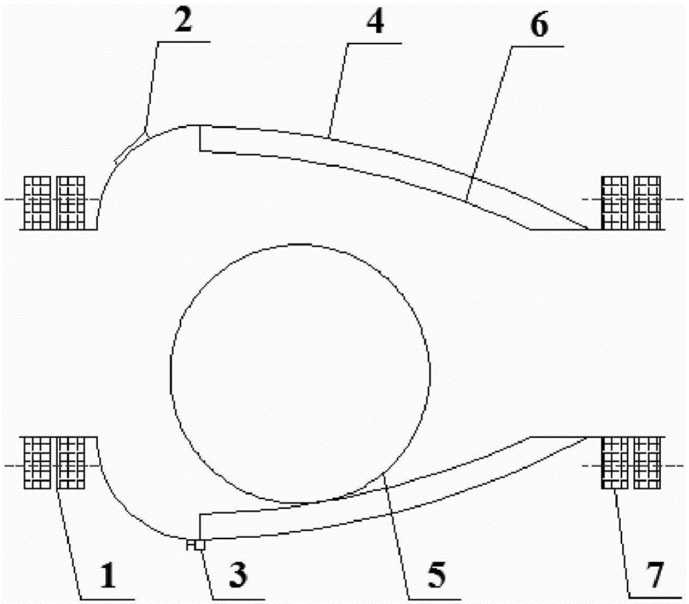
[0034] Such as figure 1 As shown, a fluid damping device to cope with sudden changes in pipeline pressure includes a window 2, a drain valve 3, a box 4, a plastic ball 5, and a grooved tube 6. The shape of the box 4 is formed by rotating an oval curve around the axis for one circle. The two ends of the rotary body are coaxially provided with an outlet, an inlet, and an upstream connecting flange 1 and a downstream connecting flange 7 for connecting the upper and lower gas pipelines. The inner wall of the box body 4 near the outlet is uniformly There are several grooved pipes 6 pointing to the outlet at intervals. The arc of the grooved pipes 6...


PUM


Abstract

The invention discloses a fluid damping device used for coping with pipeline pressure jump. The fluid damping device comprises a box body. The box body is in a shape like a rotation body, wherein an ovoid curve rotates around the axis by a cycle to form the rotation body; and the two ends of the box body are coaxially provided with an outlet, an inlet and a connecting device for connecting an upstream gas pipeline with a downstream gas pipeline. Multiple groove pipes pointing to the outlet are evenly distributed on the inner wall, close to the outlet, of the box body in a spaced manner in a peripheral direction. The radian of the groove pipes is consistent with that of the inner wall of the box body. A plastic ball is smooth in surface and is movably placed in an inner cavity of the box body. The diameter of the plastic ball is larger than the diameter of the upstream gas pipeline and the diameter of the downstream gas pipeline. By changing the circulation area and the local resistance coefficient, the response time of downstream pressure jump is prolonged, the purpose that pressure is adjusted slowly is achieved, the structure and the principle are simple and clear, the fluid damping device is easy to mount and maintain, sensitive to response and fast in adjustment, the influence of upstream pressure jump on downstream pipeline instruments and equipment is relieved, the operating cost of enterprises is lowered, and safe and stable operation of the pipelines is guaranteed.

Description

technical field [0001] The invention relates to a fluid damping device, in particular to a fluid damping device for coping with sudden changes in pipeline pressure. Background technique [0002] At present, city gas is mainly transported through the pipeline network system. When natural gas is utilized, the upstream natural gas is transported to city gas or large-scale users through the pipeline network. Due to the sudden situation of natural gas in the process of gas supply and gas transmission or the adjustment or damage of upstream equipment such as valves and pressure regulators, the pressure of natural gas in the pipeline fluctuates, which further leads to sudden changes in the flow rate. This instantaneous change is harmful to the equipment. , The surface of the instrument will cause a certain impact and vibration at the same time. In severe cases, it will affect the normal use of equipment and instruments and threaten the safe operation of gas pipelines. Therefore, su...

Claims


Application Information

Patent Timeline
Patent Type & Authority Applications(China)
IPC IPC(8): F16L55/05F16L55/055
CPCF16L55/043F16L55/05F16L55/055
Inventor 徐文东陈仲熊凡凡钟胜
Owner 广东广大新能源科技有限公司
Why Eureka
Try Eureka