Air conditioner control method, device and system and air conditioner controller

A control method and air-conditioning technology, applied in heating and ventilation control systems, control input involving air characteristics, space heating and ventilation control input, etc., can solve problems such as wasting vehicle energy, increasing vehicle noise, and reducing vehicle emissions. , to achieve the effect of improving energy utilization, reducing vehicle noise, and reducing temperature fluctuations

Active Publication Date: 2016-06-01
GUANGZHOU AUTOMOBILE GROUP CO LTD
View PDF7 Cites 16 Cited by
  • Summary
  • Abstract
  • Description
  • Claims
  • Application Information

AI Technical Summary

Problems solved by technology

[0004] On the one hand, when the clutch is engaged, the compressor always refrigerates with a fixed displacement, which will consume a large amount of engine torque and waste the energy of the whole vehicle; Vehicle noise, reduce vehicle NVH (Noise, Vibration, Harshness, noise, vibration and harshness) performance; and the evaporator surface temperature TE fluctuates in the range from T3 to T4, the air conditioner controller in order to reduce the temperature of the air outlet Fluctuation, adjust the air mixing damper according to the change of evaporator temperature, but the mixing air damper is mechanically controlled, and there is a large lag, which causes the temperature of the air outlet of the air conditioner to fluctuate within a certain range, making the human body feel unable to achieve sufficient comfortable

Method used


Image

  • Air conditioner control method, device and system and air conditioner controller
  • Air conditioner control method, device and system and air conditioner controller
  • Air conditioner control method, device and system and air conditioner controller

Examples


Embodiment Construction

[0030] In order to make the object, technical solution and advantages of the present invention clearer, the present invention will be further described in detail below in conjunction with the accompanying drawings and embodiments. It should be understood that the specific embodiments described here are only used to explain the present invention, and do not limit the protection scope of the present invention.

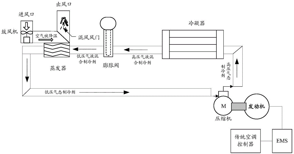
[0031] The solutions of the embodiments of the present invention can be applied to the control of automobile air conditioners. In the following description, the application to the control of automobile air conditioners is used as an example for illustration. Those skilled in the art may understand that, based on the ideas of the embodiments of the present invention, the embodiments of the present invention may also be used to control air conditioners in other scenarios.

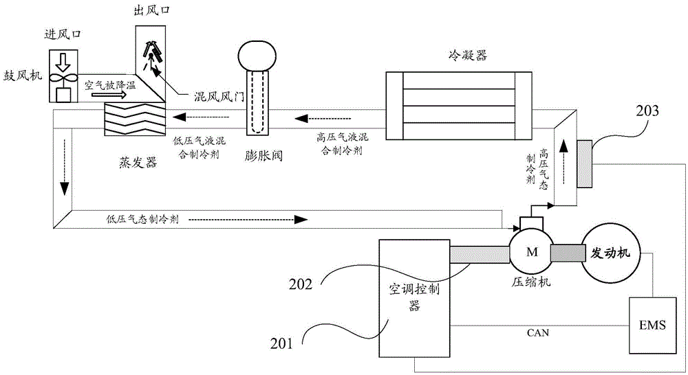
[0032] figure 2 shows a schematic structural diagram of an automobile air-conditioning system base...


PUM


Abstract

The invention discloses an air conditioner control method, device and system and a controller. The air conditioner control method comprises the steps that the set temperature of an air conditioner is obtained, and the outdoor temperature, the indoor temperature, the sunlight illuminance and the surface temperature of an evaporator are acquired; the target temperature of an air outlet is determined according to the set temperature of the air conditioner, the indoor temperature, the outdoor temperature and the sunlight illuminance, and the target temperature of the evaporator is determined according to the target temperature of the air outlet; the current control voltage is determined according to the target temperature of the evaporator, the surface temperature of the evaporator, the target temperature, obtained in the previous acquisition cycle, of the evaporator, the surface temperature, obtained in the previous acquisition cycle, of the evaporator, and the output voltage obtained in the previous acquisition cycle; and the discharge rate of a compressor is controlled according to the current control voltage. According to the air conditioner control method, device and system and the controller, automatic control over the displacement of the compressor is achieved, the control accuracy of the surface temperature of the evaporator is improved, the opening and closing frequency of a clutch is reduced, and the energy utilization rate is increased.

Description

technical field [0001] The invention relates to the field of air conditioner control, in particular to an air conditioner control method, an air conditioner control device, an air conditioner control system and an air conditioner controller. Background technique [0002] With the continuous improvement of automobile technology, the society has higher and higher requirements for the comfort and energy saving of automobiles. At present, most of the cars on the market use fixed-displacement compressors. The fixed-displacement compressors fix a displacement so that the compressor can achieve maximum cooling. When the surface temperature of the evaporator is very low, the air conditioner controller will allow the EMS (Engine Management System, Engine Management System) to cut off the clutch between the engine and the compressor to stop the compressor through the CAN (ControllerAreaNetwork, Controller Area Network) bus; When the surface temperature of the compressor rises to a hi...

Claims


Application Information

Patent Timeline
Patent Type & Authority Applications(China)
IPC IPC(8): F24F11/00
CPCF24F11/30F24F11/58F24F11/62F24F2110/10
Inventor 杨波黄少堂王明明彭飞刘嘉舜谌翔宇
Owner GUANGZHOU AUTOMOBILE GROUP CO LTD
Why Eureka
Try Eureka