Integration method and structure for cyclic utilization of river bed underflow water for water source heat pump

A technology of water source heat pump and integrated method, which is applied in the field of water circulation, can solve the problems of large footprint, impact on service life, poor source water quality, etc., and achieve the effects of small footprint, centralized management, and suitable water temperature conditions

Active Publication Date: 2016-06-01
重庆泓源渗滤取水科技有限公司
View PDF2 Cites 3 Cited by
  • Summary
  • Abstract
  • Description
  • Claims
  • Application Information

AI Technical Summary

Problems solved by technology

[0003] For surface water source heat pumps, the main problems are: 1. The source water quality is poor, and the content of mud and sand is high, so corresponding water quality treatment must be carried out
The water treatment facility occupies a large area and the project cost is high. The waste water and mud sand produced by the water treatment will also cause secondary pollution to the environment; 2. The temperature difference between the water temperature and the air temperature is small and fluctuates with the change of the temperature. Large flow and small temperature difference; 3. The water level of the river varies greatly with the seasons. The water intake pump room and the water intake head set in the water will have a certain impact on shipping, flood discharge and landscape; 4. The unit needs to be equipped with an automatic cleaning device, and the service life is limited. Certain impact, maintenance is more difficult; 5. The water demand per unit is large, the floor area is large, and the project cost is high
[0004] For groundwater water source hea

Method used


Image

  • Integration method and structure for cyclic utilization of river bed underflow water for water source heat pump

Examples


Embodiment Construction

[0022] The specific embodiments of the present invention will be further described below in conjunction with the accompanying drawings. It should be noted here that the descriptions of these embodiments are used to help understand the present invention, but are not intended to limit the present invention. In addition, the technical features involved in the various embodiments of the present invention described below may be combined with each other as long as they do not constitute a conflict with each other.

[0023] An integrated method for using river bed subsurface water for water source heat pump recycling, comprising the following steps:

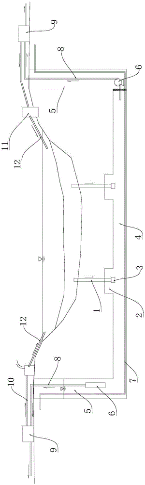
[0024] Water intake: excavate a water intake well 2 and a water delivery channel 4 connected with the water intake well 2 under the sand and pebble layer of the river bed, set a water intake structure 1 in the water intake well 2, and use the water intake structure 1 to drain the riverbed subsurface water to lead to the water intake wel...


PUM


Abstract

The invention discloses an integration method and structure for cyclic utilization of river bed underflow water for a water source heat pump. One or more water taking wells are arranged at the bottom of a river bed; and a water taking structure is mounted to a water layer of the river bed from the water taking wells for sucking the river bed underflow water. The river bed underflow water is conveyed to a water collecting well, is directly conveyed to a water source heat pump unit through a water taking pump arranged in the water collecting well, and exchanges heat in the water source heat pump unit; and returned water can perform potential energy recovery power generation by using the terrain and a certain water current speed, or is directly used for urban afforestation, firefighting , production water and landscape water to form multiple purposes. The water used by power generation or urban landscapes can be directly drained to the water taking river bed, and is renewedly filtered by a sand and gravel layer of the river bed to form the river bed underflow water again for recycling. The method can develop the river bed underflow water in large scale, is proper in water temperature condition, is free of environmental geology problems, is small in floor area, is concentrated in management, and has multiple purposes.

Description

technical field [0001] The invention relates to the technical field of water circulation, in particular to an integrated method and an integrated structure for water source heat pump recycling of subsurface water in a river bed. Background technique [0002] At present, the water source heat pump is an air-conditioning technology that uses the solar energy stored in the earth's water as a cold and heat source for conversion, and belongs to the category of renewable energy. The existing water source heat pump systems can be divided into seawater source heat pumps, surface water source heat pumps and groundwater source heat pumps according to different water sources. The water source heat pumps commonly used in my country are mainly surface water source heat pumps and groundwater source heat pumps. According to the operation of the water source heat pump, whether it is a surface water source heat pump or an underground water source heat pump, there are many problems in water i...

Claims


Application Information

Patent Timeline
IPC IPC(8): F25B30/06F24J3/06F24V50/00
CPCF24V50/00F25B30/06
Inventor 魏民陈桦邓爽
Owner 重庆泓源渗滤取水科技有限公司
Why Eureka
Try Eureka