Back reflection structure digital X-ray crystal orientation device and X-ray detector thereof

An X-ray and detector technology, applied in the field of digital X-ray crystal orientation instrument with back reflection structure, can solve the problems of low dark noise, low detection efficiency, poor symmetry, etc., achieve low dark noise, improve precision and efficiency, and high contrast Effect

Inactive Publication Date: 2016-06-01
INST OF HIGH ENERGY PHYSICS CHINESE ACADEMY OF SCI +1
View PDF7 Cites 4 Cited by
  • Summary
  • Abstract
  • Description
  • Claims
  • Application Information

AI Technical Summary

Problems solved by technology

[0005] Above-mentioned crystal orientation instrument needs to use X-ray detector, and existing X-ray detector, when utilizing back reflection to carry out the orientation deviation angle of crystal and small-angle grain boundary angle test, its signal-to-noise ratio is low, can not improve above-mentioned Test accuracy
[0006] Existing X-ray detectors, especially large-area X-ray detectors, are expensive, and the detection cost is high, so they need to be purchased at high prices from abroad
Otherwise, only point detectors can be used, and the detection efficiency is low
[0007] However, using the traditional side-incidence back-reflection diffractometer can generally only obtain less than 1 / 2 of the number of diffraction spots, and its symmetry is poor, which causes relatively great difficulties for data analysis. However, the diffraction spots obtained by the vertical-incidence back-reflection diffraction technique are symmetrical Good performance, and using a detector with high contrast (low dark noise) can get clear diffraction spots

Method used


Image

  • Back reflection structure digital X-ray crystal orientation device and X-ray detector thereof
  • Back reflection structure digital X-ray crystal orientation device and X-ray detector thereof
  • Back reflection structure digital X-ray crystal orientation device and X-ray detector thereof

Examples


Embodiment Construction

[0061] The technical solutions in the embodiments of the present invention are clearly and completely described below according to the drawings in the embodiments of the present invention. Apparently, the described embodiments are only some of the embodiments of the present invention, not all of them. Based on the embodiments of the present invention, all other embodiments obtained by persons of ordinary skill in the art without making creative efforts belong to the protection scope of the present invention.

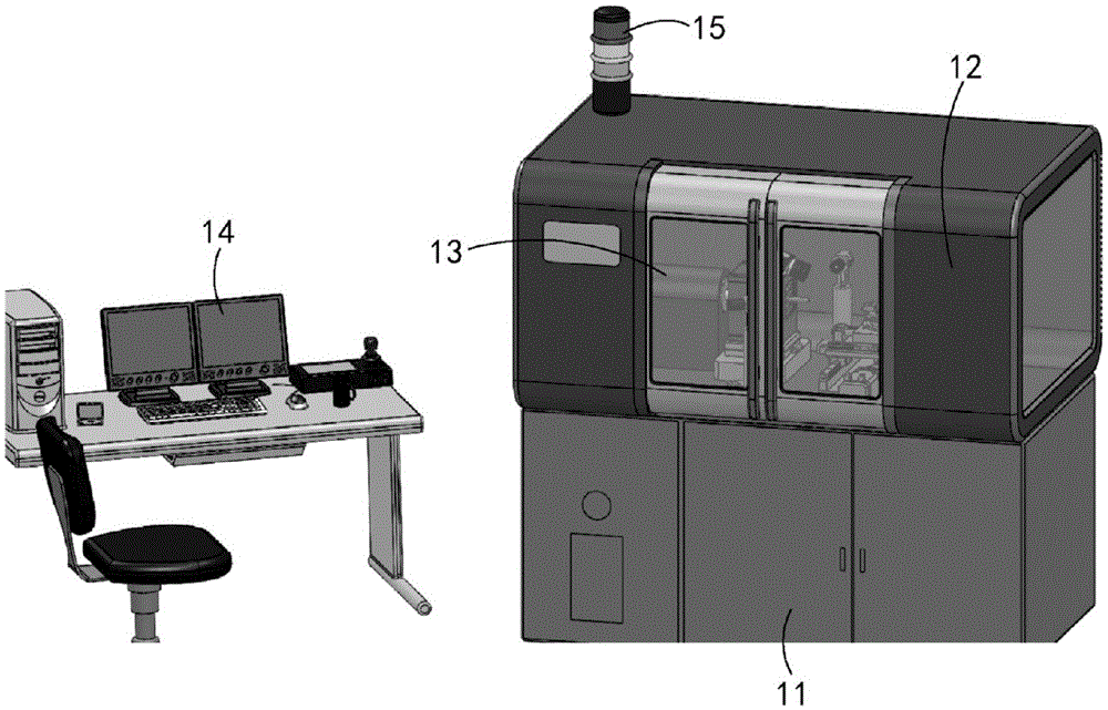
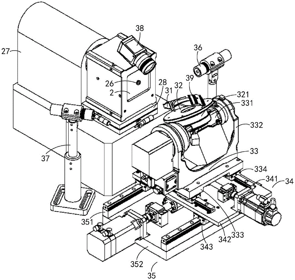
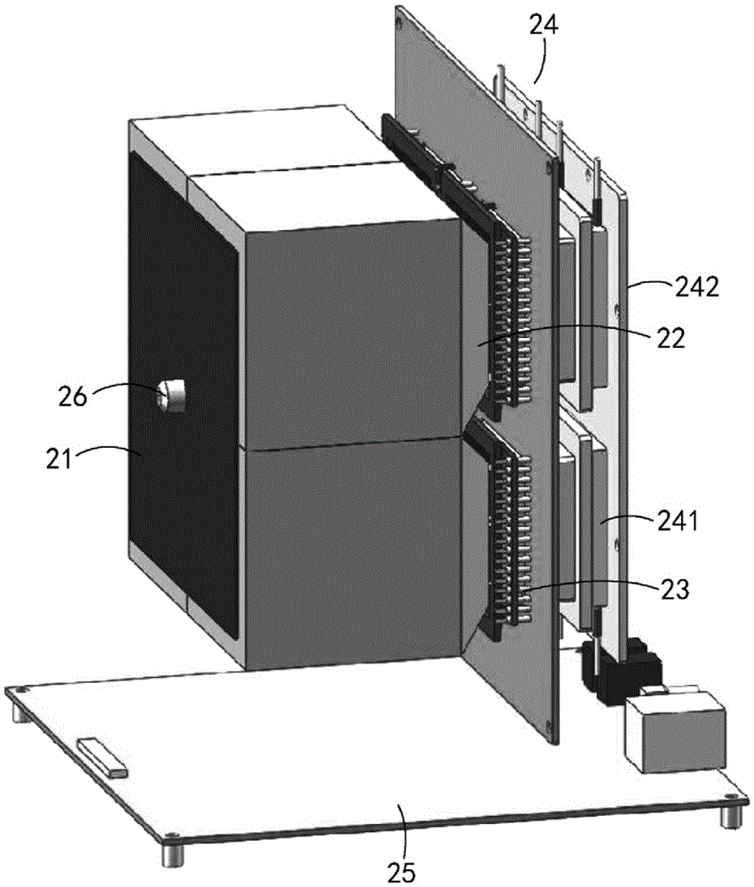
[0062] Introduce the digital X-ray crystal orientation instrument of the back reflection structure of the embodiment of the present invention below:

[0063] The back reflection structure digital X-ray crystal orientation instrument of the embodiment of the present invention is a device for qualitative and quantitative detection of solidification defects of single crystal superalloys by using digital X-rays. The digital X-ray crystal orientation instrument with back refl...


PUM

PropertyMeasurementUnit
lengthaaaaaaaaaa
diameteraaaaaaaaaa
diameteraaaaaaaaaa

Abstract

The invention discloses a back reflection structure digital X-ray crystal orientation device and an X-ray detector thereof. The X-ray detector comprises a scintillation screen, a fiber optic taper, a photosensitive element, a digital circuit board, a heat conduction element and a ray collimator, wherein a center through hole extending to the back side of the scintillation screen from the front side of the scintillation screen is formed in the scintillation screen, the fiber optic taper is connected to the back side of the scintillation screen, the photosensitive element is connected to the back side of the fiber optic taper, the rear end of the photosensitive element is connected to the front surface of the digital circuit board, the heat conduction element is connected to the rear surface of the digital circuit board and conduct heat conduction on the photosensitive element, the rear end of the ray collimator is connected to the emission end of an X-ray machine, and the front end of the ray collimator extends to the front side of the scintillation screen from the center through hole. By the adoption of the back reflection structure digital X-ray crystal orientation device and the X-ray detector thereof, orientation analysis precision and efficiency can be improved remarkably.

Description

technical field [0001] The invention relates to the technical field of X-ray imaging detection, in particular to an X-ray detector and a digital X-ray crystal orientation instrument with a back reflection structure having the X-ray detector. Background technique [0002] With the increase of the thrust-to-weight ratio of the aero-engine, the temperature of the turbine inlet will further increase. High temperature and high thrust-to-weight ratio increase the thermal and mechanical stress on the components, and put forward strict requirements on the temperature bearing capacity of the turbine component materials. Single crystal superalloy eliminates the weakening factor of grain boundary at high temperature, and its temperature bearing capacity is significantly improved, making it the preferred material for advanced aero-engine turbine components. At present, almost all advanced aero-engines are characterized by the use of single crystal superalloys. However, with the high al...

Claims


Application Information

Patent Timeline
Patent Type & Authority Applications(China)
IPC IPC(8): G01N23/207
CPCG01N23/207
Inventor 舒岩峰朱锦霞张健谢光庄凯秦秀波楼琅洪魏龙
Owner INST OF HIGH ENERGY PHYSICS CHINESE ACADEMY OF SCI
Why Eureka
Try Eureka