Multivariable time-delay system identification method based on step test

An identification method and time-delay system technology, applied in general control systems, control/regulation systems, instruments, etc., can solve the problems of test signals staying in theoretical research, identification models with high order of identification objects, and increased calculation amount

Active Publication Date: 2016-06-01
BEIJING UNIV OF CHEM TECH +1
View PDF5 Cites 8 Cited by
  • Summary
  • Abstract
  • Description
  • Claims
  • Application Information

AI Technical Summary

Problems solved by technology

[0006] However, these identification methods more or less have some deficiencies
First of all, although the identification method based on multiple integrals of differential equations can solve the identification problem of the hysteresis model, this method cannot be directly applied to the closed-loop system commonly found in industrial sites; even if this method uses the indirect method of closed-loop identification to identify the closed-loop system , will also bring about the problem that the identification model of indirect identification needs to be higher in order than the identification object
Secondly, when the frequency-domain identification method of Liu Tao et al. identifies high-order time-delay objects, it is necessary to increase the amount of calculation to obtain more accurate identification parameters.
Thirdly, some identification methods have relatively high requirements on the test signal (such as white noise or M sequence, etc.) so that these methods only stay in theoretical research, and cannot be widely used in actual industrial production

Method used


Image

  • Multivariable time-delay system identification method based on step test
  • Multivariable time-delay system identification method based on step test
  • Multivariable time-delay system identification method based on step test

Examples


Embodiment Construction

[0050] The present invention will be described in detail below in conjunction with the accompanying drawings and specific implementation examples. The specification is only used to illustrate and explain the present invention, not to limit the present invention.

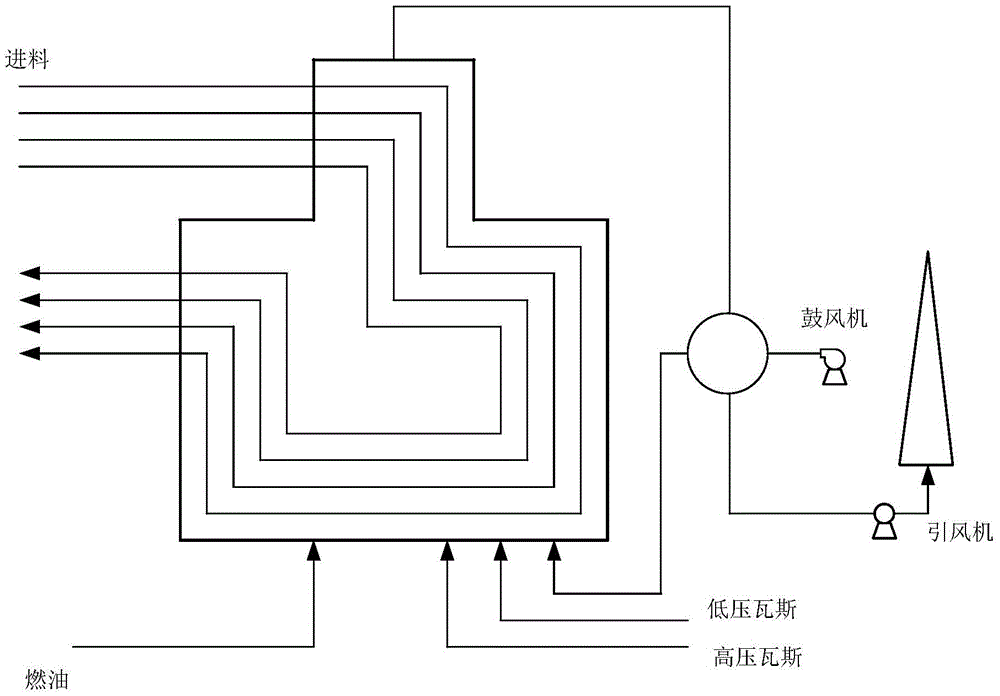
[0051] Such as figure 1 In the decompression heating furnace shown, the effects of high-pressure gas volume, feed flow rate, blast volume, etc. on the feed outlet temperature, feed load, and oxygen content in the flue gas outlet of the heating furnace are all coupled together. It is bound to have an impact on other output volumes. For this reason, it is not possible to simply correspond each control quantity to a certain controlled quantity into a single variable system, but to use a multivariable control system comprehensively to describe this problem.

[0052] This example takes a classic Wood&Berry model with strong coupling characteristics and significant hysteresis characteristics as an example to illustrate t...


PUM


Abstract

The invention discloses a multivariable time-delay system identification method based on a step test, and provides the identification method in a frequency domain mainly for a transfer function model having a pure lag step. The method is suitable for most chemical processes ( such as a pressure reduction heating furnace). The multivariable time-delay system identification method based on the step test comprises a system test unit used for stimulating an identified object to obtain input /output data for identifying; a data processing unit for carrying out noise reduction processing and the like on the data obtained through system test to enable the obtained data to be less influenced by noise, and calculating frequency domain response of the system according to the data obtained through processing; and a parameter estimation unit for carrying out linear processing on the pure lag step, then, estimating parameters through a least square method, and finally, optimizing each model parameter through iteration. The advantages of the method are that the method not only can be applied to an ordinary open-loop system, but also can be directly applied to closed-loop identification without increasing model order; identification precision is high; and the method can provide a high-precision model for a controller design engineer to design a controller.

Description

technical field [0001] The invention relates to an identification method of a multivariable time-delay system based on a step test, including an identification method for a time-delay object in the frequency domain and its application in a multivariable system based on a step test, and is mainly used in the field of process control . Background technique [0002] In the actual chemical production process, there are pure hysteresis links in many chemical processes, such as figure 1 The decompression heating furnace shown has many such pure hysteresis links. For example, it takes a while to reflect on the outlet temperature when changing the feed amount, and it takes a certain amount of time to change the negative pressure in the furnace when changing the high-pressure gas amount or induced air amount. There are corresponding changes, etc. [0003] When designing a controller, many controller design methods rely on a high-accuracy plant model, such as the internal model meth...

Claims


Application Information

Patent Timeline
Patent Type & Authority Applications(China)
IPC IPC(8): G05B17/02
CPCG05B17/02
Inventor 靳其兵何恩王琪周星孙新佳
Owner BEIJING UNIV OF CHEM TECH
Why Eureka
Try Eureka