A low-energy rotary drive device for space-borne microwave switches

A rotary drive, space-borne microwave technology, applied in waveguide-type devices, circuits, electrical components, etc., can solve the problems of low driving force, unstable contact resistance, total reflection of microwave signals, etc., to improve the reed retention force and lock. The effect of preventing torque, improving reliability and stability, and improving anti-vibration and shock performance

Active Publication Date: 2019-03-15
CHINA AEROSPACE TIMES ELECTRONICS CORP
View PDF5 Cites 0 Cited by
  • Summary
  • Abstract
  • Description
  • Claims
  • Application Information

AI Technical Summary

Problems solved by technology

[0003] Since the product is used in the aerospace environment, it must meet strict mechanical performance indicators, which involves the reed retention force when the switch is turned on. If it is less than the limit value, it will cause potential electrical contact failure, resulting in total reflection of the microwave signal. The entire chain road failure
The existing microwave switch only relies on the magnetic steel on the reed to provide the driving force because the contact is connected. Due to the limitation of electromagnetic performance and structure, the driving force is low, resulting in a low contact force, which is smaller than that of conventional relays, resulting in a decrease in contact resistance. unstable

Method used


Image

  • A low-energy rotary drive device for space-borne microwave switches
  • A low-energy rotary drive device for space-borne microwave switches
  • A low-energy rotary drive device for space-borne microwave switches

Examples


Embodiment Construction

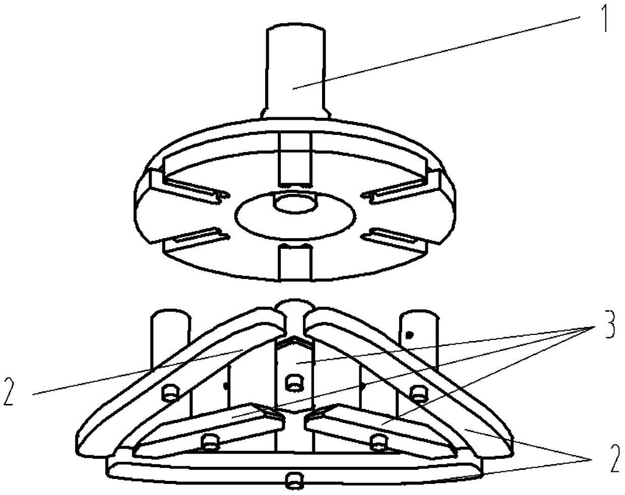
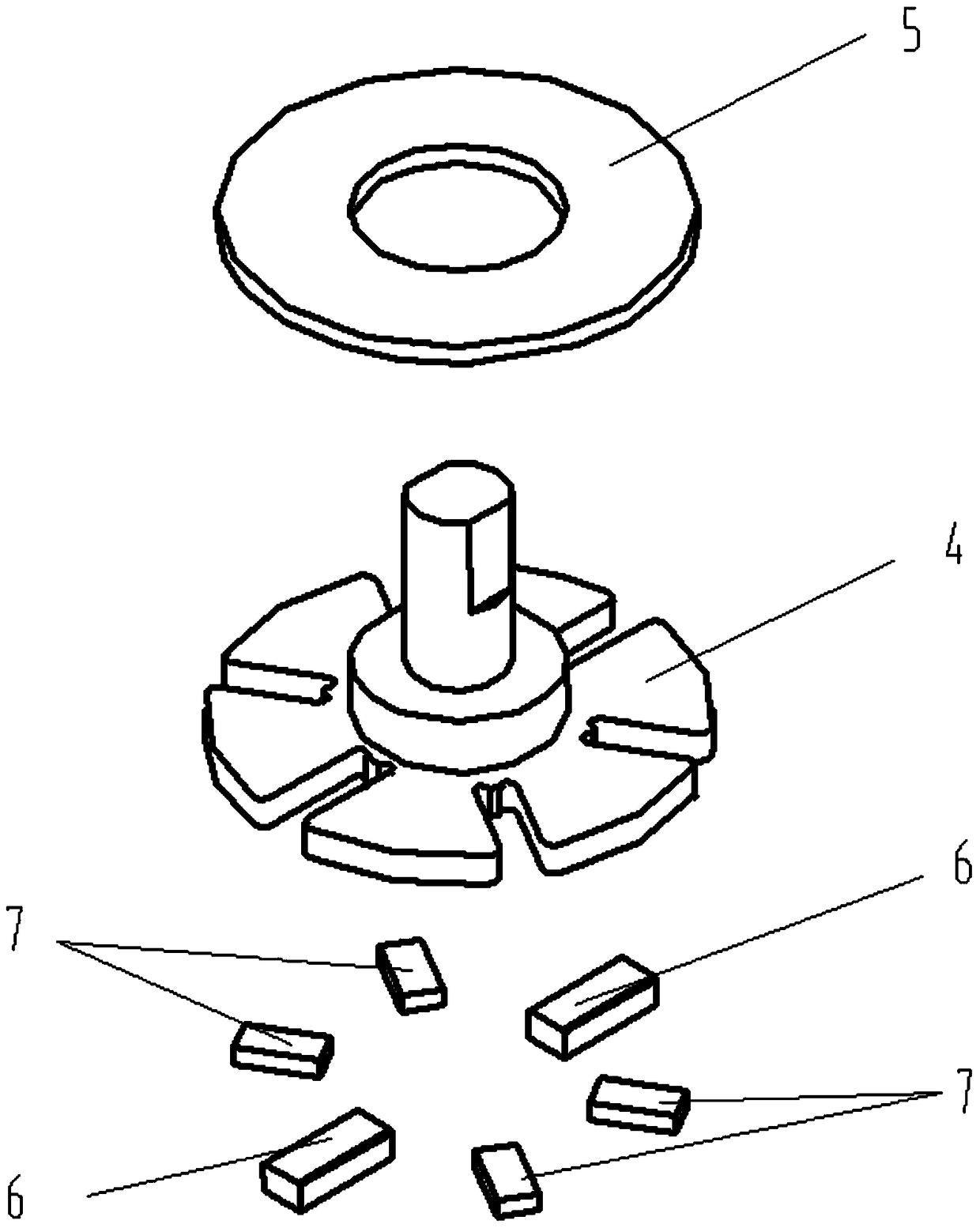
[0015] Such as figure 1 As shown, a low-energy rotary drive device for an on-board microwave switch includes a rotor set 1 , a first reed set 2 and a second reed set 3 . Such as figure 2 As shown, the rotor set 1 includes a rotor shaft 4, a rotor spacer 5, a first driving magnet 6, and a second driving magnet 7; the bottom of the rotor shaft 4 is disc-shaped, and the bottom disc has a number of concave holes along the circumferential direction. Groove, there is a cylindrical structure in the middle of the disk, and the cylindrical structure is composed of two cylinders with different diameters to form a step; the rotor gasket 5 is a circular or elliptical ring, which is sleeved on the cylindrical structure in the middle of the rotor shaft 4 and fixed On the upper surface of the bottom disk of the rotor shaft 4; the first drive magnet 6 and the second drive magnet 7 are cuboids, which are permanent magnets with opposite polarities after magnetization. The first drive magnet 6...


PUM


Abstract

A low-energy-consumption rotation driving apparatus for a satellite-borne microwave switch is disclosed. The low-energy-consumption rotation driving apparatus comprises first driving magnetic steels (6) and the like; a rotor spacer (5) is fixed on the upper surface of a circular disc at the bottom of a rotor shaft (4); the first driving magnetic steels (6) and second driving magnetic steels (7) are connected with the rotor spacer (5) and are mounted in a groove in the circular disc at the bottom of the rotor shaft (4); a first reed driving rod (9) is mounted in the middle of a first reed (10), and perpendicular to the first reed (10); first reed magnetic steel (8) is mounted in the first reed driving rod (9); a second reed driving rod (12) is mounted in the middle of a second reed (13), and perpendicular to the second reed (13); second reed magnetic steel (11) is mounted in the second reed driving rod (12); and a first reed group (2) or a second reed group (3) is arranged under each first driving magnetic steel (6) or each second driving magnetic steel (7) respectively. According to the low-energy-consumption rotation driving apparatus, the energy consumption of the microwave switch driving system is lowered, and the operating stability of the microwave switch is improved.

Description

technical field [0001] The invention relates to a drive device for a satellite-borne microwave switch, which belongs to the field of mechanical design. Background technique [0002] The main function of the satellite-borne microwave switch is to realize the transmission and switching of the microwave signal path of the satellite system. It is a device that uses vacuum isolation and switches microwave signals through mechanical actions. The radio frequency structure of the electromechanical microwave switch for aerospace uses the electrical contact structure of the reed contact, and the on-off switching control of the microwave signal is realized through the on-off of the reed and the conductor contact. [0003] Since the product is used in the aerospace environment, it must meet strict mechanical performance indicators, which involves the reed retention force when the switch is turned on. If it is less than the limit value, it will cause potential electrical contact failure,...

Claims


Application Information

Patent Timeline
Patent Type & Authority Patents(China)
IPC IPC(8): H01P1/11
CPCH01P1/11
Inventor 田亚伟王文涛张楚贤苌群峰刘洪姜东明
Owner CHINA AEROSPACE TIMES ELECTRONICS CORP
Why Eureka
Try Eureka