
Electromagnetic band gap structure based dual-frequency microstrip array antenna with high isolation

A technology with electromagnetic bandgap structure and high isolation, which is applied in the directions of antenna arrays, antennas, and antenna couplings that are energized separately. It can solve the problems of deterioration of antenna polarization characteristics, efficiency of array mismatching units, and reduction, and achieve high isolation. degree of effect

Inactive Publication Date: 2016-06-01
张晓燕
View PDF5 Cites 32 Cited by
  • Summary
  • Abstract
  • Description
  • Claims
  • Application Information

AI Technical Summary

Problems solved by technology

In an existing dual-band microstrip array antenna, there is a mutual coupling effect between the microstrip antennas. The existence of mutual coupling will lead to: ① the pattern of the elements in the array is different from that of the isolated elements; ② the elements in the array The input impedance of the input impedance of the array is different from that of the isolated element; ③For the phased array, the input impedance of the elements in the array will change with the scan angle, which will cause the mismatch of the array and the reduction of the efficiency of the elements; ④The polarization characteristics of the antenna will also change go bad

Method used


Image

  • Electromagnetic band gap structure based dual-frequency microstrip array antenna with high isolation
  • Electromagnetic band gap structure based dual-frequency microstrip array antenna with high isolation
  • Electromagnetic band gap structure based dual-frequency microstrip array antenna with high isolation

Examples


Embodiment Construction

[0015] In order to deepen the understanding of the present invention, the present invention will be further described below in conjunction with the embodiments and accompanying drawings. The embodiments are only used to explain the present invention and do not constitute a limitation to the protection scope of the present invention.

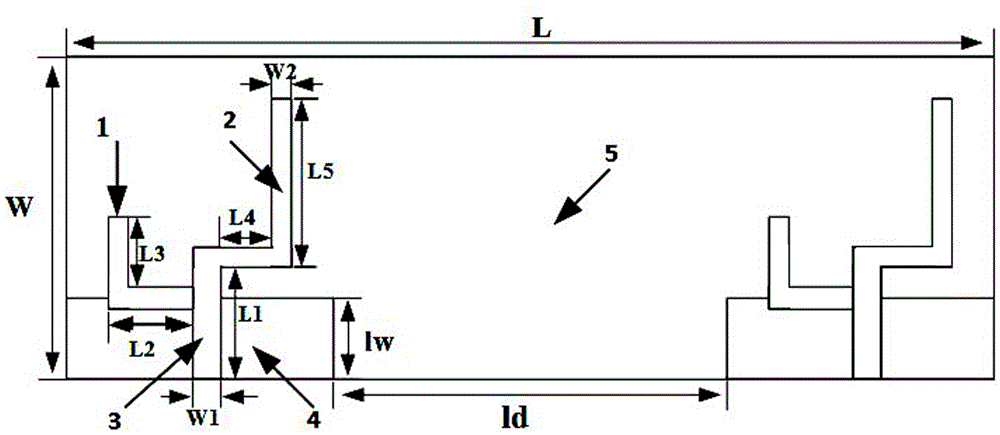
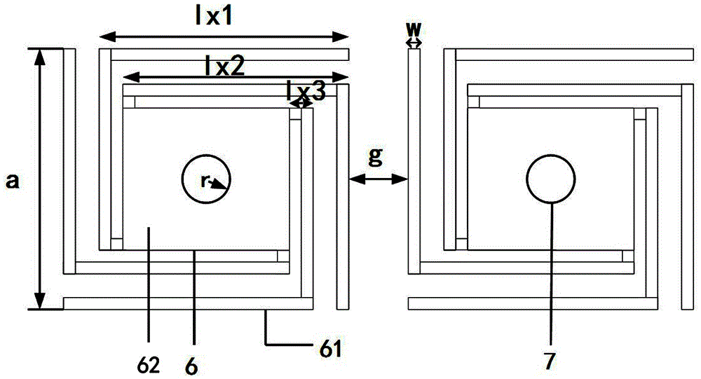
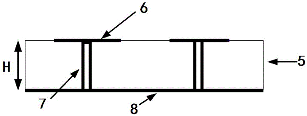
[0016] A dual-frequency microstrip array antenna with high isolation based on the electromagnetic bandgap structure of the present invention, such as Figure 4 As shown, it includes two elements of the array antenna and an array of L-shaped electromagnetic bandgap units loaded between the two elements. The two elements and the array of L-shaped electromagnetic bandgap elements are all supported on the FR4 dielectric substrate 5. The L-shaped The distance dd between the array of electromagnetic bandgap units and adjacent elements is 19.375mm. figure 1 As shown, each element includes high-frequency monopole 1, low-frequency monopole 2, microstrip f...


PUM


Abstract

The invention discloses an electromagnetic band gap structure based dual-frequency microstrip array antenna with high isolation. The dual-frequency microstrip array antenna comprises two oscillators of the array antenna and an L-shaped electromagnetic band gap unit organized array, wherein the L-shaped electromagnetic band gap unit organized array is loaded between the two oscillators, the two oscillators and the L-shaped electromagnetic band gap unit organized array are all supported on a FR4 dielectric substrate, each oscillator comprises a high-frequency monopole, a low-frequency monopole, a microstrip feeder line and metal ground, the high-frequency monopole and the lower-frequency monopole are connected with the microstrip feeder line, the microstrip feeder line is inserted into the metal ground, the L-shaped electromagnetic band gap unit organized array comprises a plurality of L-shaped electromagnetic bang gap units arranged in an array, each L-shaped electromagnetic band gap unit comprises an electromagnetic band gap metal patch, and the electromagnetic band gap metal patch is connected with a ground floor on other side via a conductive via hole in the middle. In the dual-frequency microstrip array antenna, the working frequency band is 2.27-2.67GHz and 5.29-7.09GHz, and the frequency band range of WLAN is completely covered; and the electromagnetic band gap structure with dual-band gap characteristic is loaded between oscillator units, and thus, the antenna has relatively high isolation in dual frequency bands.

Description

technical field [0001] The invention relates to a microstrip array antenna, in particular to a dual-frequency microstrip array antenna with high isolation based on an electromagnetic bandgap structure. Background technique [0002] With the continuous development of communication technology and the further improvement of user needs, in many cases, antennas are required to not only work in one frequency band, such as radar and communication systems such as Synthetic Aperture Radar (SAR) and Global Positioning System (GPS) often require antennas to be able to It has dual-frequency or even multi-frequency working characteristics. In an existing dual-band microstrip array antenna, there is a mutual coupling effect between the microstrip antennas. The existence of mutual coupling will lead to: ① the pattern of the elements in the array is different from that of the isolated elements; ② the elements in the array The input impedance of the input impedance of the array is different...

Claims


Application Information

Patent Timeline
IPC IPC(8): H01Q1/52H01Q21/06
CPCH01Q5/20H01Q1/523H01Q21/061
Inventor 张晓燕王传云滕兆朋马海涛刘志伟喻易强田苗
Owner 张晓燕
Learn More