Connector and connection method of graphite composite grounding bodies

A technology of composite grounding and connection method, applied in the field of power system, can solve the problems of inapplicability of electric welding, gas welding and exothermic welding, and achieve the effect of meeting the actual grounding construction requirements, low connection resistance and high connection strength

Inactive Publication Date: 2016-06-01
FOSHAN POWER SUPPLY BUREAU GUANGDONG POWER GRID +1
View PDF4 Cites 3 Cited by
  • Summary
  • Abstract
  • Description
  • Claims
  • Application Information

AI Technical Summary

Problems solved by technology

However, graphite composite grounding body is different from metal grounding materials, so it is not suitable for electric welding, gas welding and exothermic welding

Method used


Image

  • Connector and connection method of graphite composite grounding bodies
  • Connector and connection method of graphite composite grounding bodies

Examples


Embodiment 1

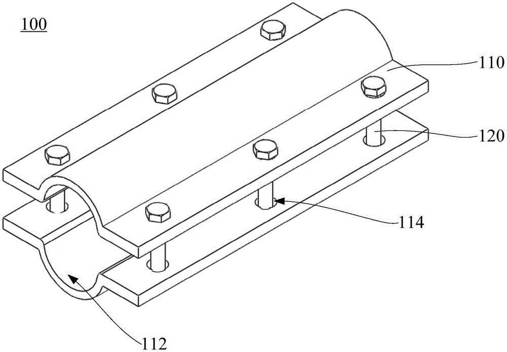
[0027] The connector 100 of the graphite composite grounding body of the first embodiment includes a conductive splint 110 , a bolt 120 , a nut (not shown in the figure) and a washer (not shown in the figure). The graphite composite grounding body of this embodiment can be used to connect graphite composite grounding materials with a diameter of 28mm, such as the connection of flexible graphite composite grounding materials disclosed in the patent CN203521649U "New Graphite Composite Grounding Material".

[0028] There are two conductive splints 110 . The length of the two conductive splints 110 is 150mm, the width is 70mm, and the thickness is 5mm. The middle parts of the two conductive splints 110 are provided with arc-shaped arches 112 . The interior of the arch 112 forms a slot for accommodating the graphite composite grounding body. The diameter of the arch 112 is consistent with the diameter of the graphite composite grounding body to be connected, which is also 28mm. ...

Embodiment 2

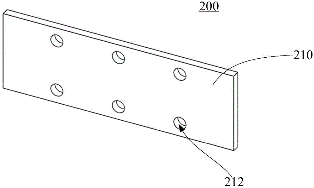
[0031] The connector 200 of the graphite composite grounding body of the second embodiment includes a conductive splint 210 , bolts (not shown), nuts (not shown) and washers (not shown). The graphite composite grounding body of this embodiment can be used to connect low-skin effect graphite composite grounding materials with a diameter of 40mm, such as the connection of low skin effect graphite composite grounding materials disclosed in the patent CN203521648U "Low Skin Effect Graphite Composite Grounding Material".

[0032] There are two conductive splints 210 . The conductive splint 210 is a flat structure. The length of the two conductive splints 210 is 150mm, the width is 70mm, and the thickness is 5mm. Three pairs of fixing holes 212 are provided on two sides of each conductive clip 210 . The diameter of each fixing hole 212 is 10.2mm.

[0033] The conductive splint 210 is made of stainless steel. Bolts, nuts and gaskets are made of fiberglass. There can be two nuts,...


PUM


Abstract

The present invention relates to a connector and connection method used for connecting a plurality of graphite composite grounding bodies. The connector comprises two conductive clamping plates, and bolts, nuts and spacers which are used to connect the two conductive clamping plates fixedly. The two sides of the conductive clamping plates are respectively equipped with a plurality of fixing holes which are arranged at equal intervals and through which the bolts can penetrate, and the fixing holes at the two sides of the conductive clamping plates are in one-to-one correspondence respectively. The two conductive clamping plates are used to clamp the graphite composite grounding bodies by the cooperation of the bolts, the nuts and the spacers, and connect the plurality of graphite composite grounding bodies electrically. The connector of the graphite composite grounding bodies can be widely used in the connection field of the graphite composite grounding materials, can solve the problems that the conventional graphite composite grounding bodies can not be connected by the electrowelding, gas welding, heat-released jointing, etc., can connect the graphite composite grounding bodies more stably, is large in connection intensity and low in connection resistance of connection points, and can satisfy the actual grounding construction demands.

Description

technical field [0001] The invention relates to the field of power systems, in particular to a connector and a connection method for a graphite composite grounding body. Background technique [0002] The grounding device of the power system is an important facility to ensure the reliable grounding of power equipment and protect the personal safety of power construction personnel, and it is also an important means of lightning protection for power systems. At present, the grounding materials of common power systems are mostly made of round steel, flat steel, galvanized steel and other steel materials, and some important power hubs also use expensive copper materials as grounding materials. In recent years, copper-clad steel grounding materials have also been tried in some grounding occasions. The actual operation experience shows that the copper metal grounding material has better corrosion resistance. The corrosion resistance of copper-clad steel grounding materials depend...

Claims


Application Information

Patent Timeline
Patent Type & Authority Applications(China)
IPC IPC(8): H01R4/46H01R43/027H01R4/66
Inventor 詹清华肖微吴焯军龚若涵
Owner FOSHAN POWER SUPPLY BUREAU GUANGDONG POWER GRID
Why Eureka
Try Eureka