A positioning method for upfc damping control

A positioning method and damping control technology, applied in the field of control, can solve problems such as the difficulty that modal analysis cannot express the source, distribution and transmission of indicators, and the inability to clearly express the power system, and achieve the effect of clear guidance

Inactive Publication Date: 2018-04-06
JIANGSU ELECTRIC POWER CO +1
View PDF4 Cites 0 Cited by
  • Summary
  • Abstract
  • Description
  • Claims
  • Application Information

AI Technical Summary

Problems solved by technology

This kind of modal analysis cannot express the physical process of the source, distribution and transmission of the index, that is, it cannot clearly express the physical process of the power system, so this kind of modal analysis is often difficult to analyze and explore the selection of UPFC damping control signals

Method used


Image

  • A positioning method for upfc damping control
  • A positioning method for upfc damping control
  • A positioning method for upfc damping control

Examples


Embodiment Construction

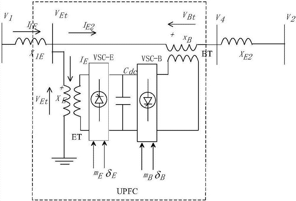
[0057] As shown in the figure, a positioning method for UPFC damping control includes the following steps:

[0058] (1) Collect data; collect the internal reactance data and excitation system data of the generator, and obtain the steady-state data and static data of the power system through the receipt collection and monitoring system SCADA system and the energy management system EMS;

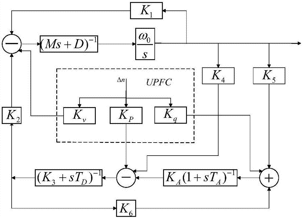
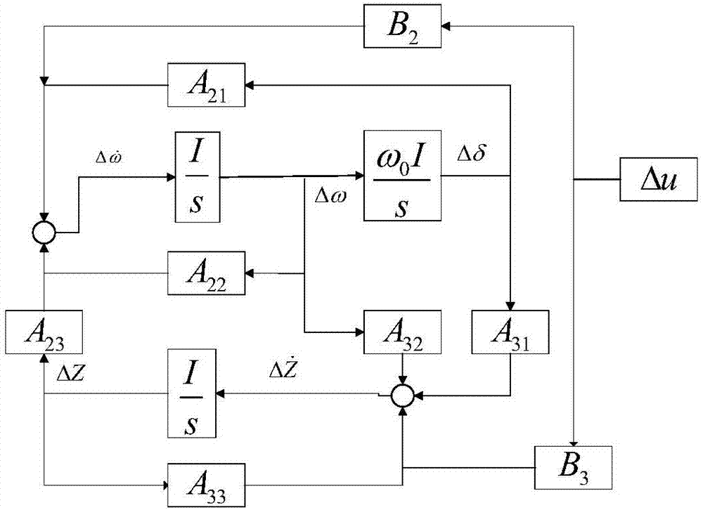
[0059] (2) Calculate the linearization matrix of the open-loop system comprising UPFC;

[0060]

[0061] In the formula, Δm E ,Δδ E ,Δm B ,Δδ B is the linearized UPFC input control signal, δ is the generator power angle state variable vector, ω is the generator speed state variable vector, E q is the no-load electromotive force of the excitation current, E fd is the generator excitation voltage, V DC is the UPFC DC capacitor voltage; Δ is the linearization operator, and adding points to the variable is the differential operator; M is the diagonal matrix of the generator inertia constan...


PUM


Abstract

The invention discloses a positioning method for UPFC damping control. Positioning of a UPFC stability controller is carried out by a damping matrix decomposition analysis method DTA according to a whole-system linear model, so that DTA calculation result is associated with a damping torque provided to a generator in a power system by a controller and the participation property of the generator into a specified electromechanical oscillation mode; and the physical significance is relatively clear. The positioning method has the beneficial effect that the process that the controller affects the specified electromechanical oscillation mode of the power system is specifically provided, so that a guidance with clear physical significance is provided for selecting a stable signal of the controller.

Description

technical field [0001] The invention relates to the technical field of control, in particular to a positioning method for UPFC damping control. Background technique [0002] The Unified Power Flow Controller (UPFC) is by far the most powerful FACTS device, which is mainly composed of an excitation transformer (Excitation Transformer, ET), a boosting transformer (Boosting Transformer, BT), two three-phase voltage Converter (Voltage Source Converter, VSC) and a DC link capacitor, its structure is as follows figure 1 shown. m E ,m B and δ E ,δ B They are the amplitude adjustment ratio and phase angle of the parallel voltage source inverter and the series voltage source inverter respectively, which are used as the control signal input of UPFC, and different functions such as power flow control and voltage regulation are respectively completed through certain control strategies. Each control loop of UPFC can be equipped with an additional damping controller to suppress the ...

Claims


Application Information

Patent Timeline
Patent Type & Authority Patents(China)
IPC IPC(8): H02J3/00
Inventor 陈中徐贤周涛
Owner JIANGSU ELECTRIC POWER CO
Why Eureka
Try Eureka