Gas turbine

A gas turbine and combustion gas technology, which is applied in the direction of gas turbine devices, mechanical equipment, engine functions, etc., can solve the problems of reduced driving force recovery efficiency and gas turbine performance, and achieve the effect of suppressing the reduction of recovery efficiency and improving performance

Active Publication Date: 2016-06-01
MITSUBISHI POWER LTD
View PDF6 Cites 9 Cited by
  • Summary
  • Abstract
  • Description
  • Claims
  • Application Information

AI Technical Summary

Problems solved by technology

On the other hand, the gas turbine has the following problems: when the rated operation is reached, the gap between the tip of the rotor blade and the inner wall surface of the segm

Method used


Image

  • Gas turbine
  • Gas turbine
  • Gas turbine

Examples


Embodiment Construction

[0044] Hereinafter, preferred embodiments of the gas turbine according to the present invention will be described in detail with reference to the drawings. In addition, this invention is not limited to this embodiment, Moreover, when there are several embodiment, the structure which combined each embodiment is included.

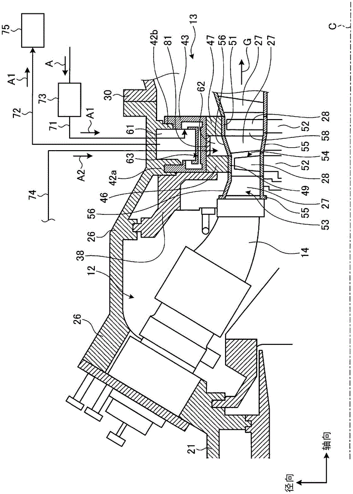
[0045] Figure 7 It is a schematic diagram showing the overall configuration of the gas turbine according to the present embodiment.

[0046] Such as Figure 7 As shown, the gas turbine of this embodiment is constituted by a compressor 11 , a combustor 12 and a turbine 13 . The gas turbine is coaxially connected with a generator (not shown), and can generate electricity.

[0047] The compressor 11 has an air inlet 20 for introducing air, and inlet guide vanes (IGV: Inlet Guide Vane) 22 are arranged in the compressor chamber 21, and are arranged alternately along the flow direction of the air (the axial direction of the rotor 32 described later). A plurali...


PUM


Abstract

A gas turbine provided with: a blade ring (43) that marks off an annular first cavity (61) as a result of being connected to the inner periphery of a turbine casing (26); a plurality of heat-insulating rings (46, 47) that are connected to the inner periphery of the blade ring (43) at a predetermined axial direction interval; a plurality of partitioning rings (49, 51) that are connected to the inner periphery of the plurality of heat-insulating rings (46, 47); a plurality of rotor blade bodies (54) that are spaced at a predetermined axial direction interval, are affixed to the outer periphery of a rotor (32), and are arranged so as to face the plurality of partitioning rings (49, 51) in the radial direction; a plurality of stator blade bodies (53) that mark off an annular second cavity (62) as a result of an exterior shroud (56) being affixed to the heat-insulating rings (46, 47) between the plurality of rotor blade bodies (54); a second cooling-air supply route (74) that supplies compressed air to the second cavity (62); a first cooling-air supply route (71) that supplies cooling air that has a lower temperature than the compressed air to the first cavity (61); and a cooling-air discharge route (72) that discharges the cooling air from the first cavity (61). The gas turbine thereby provides an appropriate amount of clearance between rotor blades and the side of a turbine casing and has improved performance.

Description

technical field [0001] The present invention relates to, for example, a gas turbine for supplying fuel to compressed high-temperature and high-pressure air to combust it, and supplying the generated combustion gas to a turbine to obtain rotational power. Background technique [0002] A typical gas turbine consists of a compressor, a combustor, and a turbine. The compressor compresses the air introduced from the air inlet to make it high-temperature and high-pressure compressed air. The combustor supplies fuel to the compressed air and combusts it, thereby obtaining high-temperature and high-pressure combustion gas. The turbine is driven by the combustion gas to drive a coaxially connected generator. [0003] The turbine in this gas turbine is configured by arranging a plurality of stationary blades and moving blades alternately along the flow direction of the combustion gas in the casing, and the combustion gas generated in the combustor is driven by passing through the pl...

Claims


Application Information

Patent Timeline
IPC IPC(8): F02C7/18F01D11/08F01D17/08F02C7/28
CPCF01D11/24F05D2260/213F01D25/14F01D25/246F05D2240/15F05D2260/231F01D5/02F01D9/041F01D25/10F01D25/12F01D25/24F02C3/04F02C7/18F02C7/24F02C9/18F05D2220/32F05D2240/35
Inventor 桥本真也
Owner MITSUBISHI POWER LTD
Why Eureka
Try Eureka