

Electrostatic surface laying layer system manufactured through powder bed additive
A technology of additive manufacturing and surface layering, which is applied in the field of additive manufacturing, can solve the problems of long warm-up time, uneven thickness of the powder coating surface, and poor compactness of parts, so as to improve the density of parts and accurately control powder coating The effect of avoiding warping and deformation
- Summary
- Abstract
- Description
- Claims
- Application Information
AI Technical Summary
Problems solved by technology
Method used
Image

Examples
Embodiment Construction
[0021] The present invention will be further described in detail below in conjunction with the accompanying drawings.
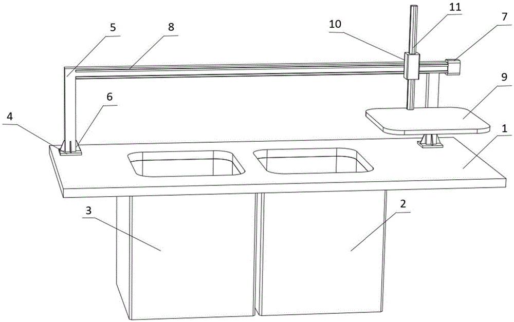
[0022] refer to figure 1 , an electrostatic surface laying system for powder bed additive manufacturing, including a formed work surface 1, a powder supply cylinder 2 and a forming cylinder 3 are arranged below the work surface 1, and a truss is connected above the work surface 1 through a connecting plate 4 Mechanism 5, rib plate 6 is connected between connecting plate 4 and truss mechanism 5, slide rail 8 is arranged on truss mechanism 5, slide rail 8 cooperates with slider 10, guide rod 11 is connected on slider 10, guide rod 11 The bottom is connected with the electrode powder pressing plate 9, the slider 10 and the guide rod 11 realize the movement of the electrode pressing powder plate 9 up and down, and the slider 10 is controlled by the stepping motor 7 connected to the end of the slide rail 8 to realize the electrode pressing plate 9 To move left an...
PUM
 Abstract
Description
Claims
Application Information