Rotary cutting tool

A technology of cutting tools and cutting parts, applied in the direction of manufacturing tools, milling cutting blades, metal processing equipment, etc., can solve problems such as deformation of the front end of the milling cutter, twisting and deformation of the cutting edge of the milling cutter, and dimensional deviation, so as to ensure processing efficiency and increase Actual area, good processing effect

Inactive Publication Date: 2016-06-08
SHENZHEN JINZHOU PRECISION TECH
View PDF5 Cites 5 Cited by
  • Summary
  • Abstract
  • Description
  • Claims
  • Application Information

AI Technical Summary

Problems solved by technology

Rotary cutting tools (micro milling cutters) are used to process the shape and cutting of printed circuit boards. In CNC machining, multi-layer circuit boards are usually stacked and processed, that is, multi-layer circuit boards are processed at one time, and the efficiency is high. Due to the rotary cutting tool The performance is not good. The existence of processing torque and torque causes the cutting edge of the milling cutter to be distorted and deformed. The front end of the milling cutter is deformed more seriously, resulting in a certain dimensional deviation between the stacked upper plate and the lower plate. The processing effect is not good and affects the circuit. The actual processing benefit of the board manufacturer

Method used


Image

  • Rotary cutting tool
  • Rotary cutting tool
  • Rotary cutting tool

Examples


Embodiment Construction

[0023] In order to make the object, technical solution and advantages of the present invention clearer, the present invention will be further described in detail below in conjunction with the accompanying drawings and embodiments. It should be understood that the specific embodiments described here are only used to explain the present invention, not to limit the present invention.

[0024] It should be noted that when an element is referred to as being “fixed on” or “disposed on” another element, it may be directly on the other element or there may be an intervening element at the same time. When an element is referred to as being "connected to" another element, it can be directly connected to the other element or intervening elements may also be present.

[0025] It should also be noted that the orientation terms such as left, right, up, and down in the embodiments of the present invention are only relative concepts or refer to the normal use state of the product, and should ...


PUM


Abstract

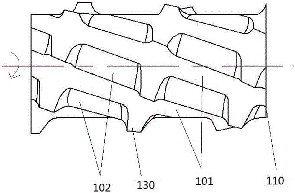
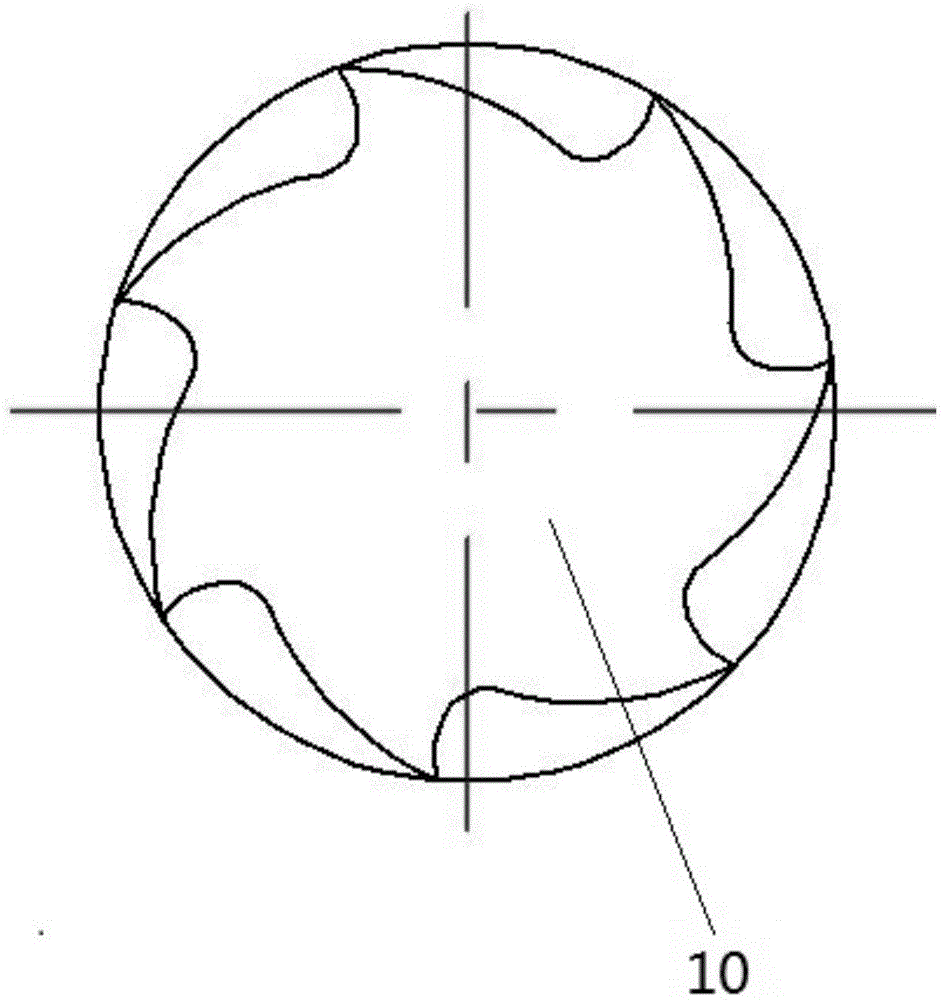
The invention is suitable for the technical field of cutting tools and particularly suitable for the technical field of micro drill bits for milling edges of printed circuit boards, and discloses a rotary cutting tool. The rotary cutting tool comprises a cutting part which has a taper; the diameter of the front end of the cutting part is smaller than that of the rear end of the cutting part; the cutting part is provided with a plurality of main spiral grooves of the same spiral angle; the main spiral grooves are evenly distributed in the circumferential direction, and the screwing direction of each main spiral groove is rightwards; the cutting part is further provided with an auxiliary spiral groove which comprises a leftwards-screwed spiral groove spirally ascending from the front end to the rear end of the cutting part; the auxiliary spiral groove spirally ascending and the main spiral grooves form a plurality of cutting teeth on the cutting part; and in the spiral direction of the auxiliary spiral groove, the tooth width portions between the adjacent cutting teeth coincide with one another. According to the rotary cutting tool, the auxiliary spiral groove of the cutting part is of a leftwards-screwed structure, and the main spiral grooves of the cutting part are of rightwards-screwed structures. The actual area of the cross section of each spiral groove is increased, chip blockage is not likely to happen, the service life can be prolonged by 86.24%, and precision can be improved by 33.89%.

Description

technical field [0001] The invention belongs to the technical field of cutting tools, in particular to a rotary cutting tool. Background technique [0002] As the electronic equipment industry pursues thinner and faster development, the processing requirements for printed circuit boards are getting higher and higher. Therefore, improving processing efficiency and processing accuracy is crucial to the development of the entire industry. Rotary cutting tools (micro milling cutters) are used to process the shape and cutting of printed circuit boards. In CNC machining, multi-layer circuit boards are usually stacked and processed, that is, multi-layer circuit boards are processed at one time, and the efficiency is high. Due to the rotary cutting tool The performance is not good. The existence of processing torque and torque causes the cutting edge of the milling cutter to be distorted and deformed. The front end of the milling cutter is deformed more seriously, resulting in a cer...

Claims


Application Information

Patent Timeline
Patent Type & Authority Applications(China)
IPC IPC(8): B23C5/10
CPCB23C5/10B23C2200/0472B23C2200/32B23C2210/0407B23C2210/0485
Inventor 屈建国李凯邹卫贤张辉王磊
Owner SHENZHEN JINZHOU PRECISION TECH
Why Eureka
Try Eureka