An oil and gas pipeline restraint simulation device and its testing method
A technology for oil and gas pipelines and simulation devices, which is applied to tubular objects, other household appliances, applications, etc., can solve the problem of not having the ability to simulate large restraint and restraint stress, unable to simulate the restraint degree of oil and gas pipelines, and inability to simulate large restraint stress and other problems, to achieve the effect of convenient welding operation, stable installation and easy positioning
- Summary
- Abstract
- Description
- Claims
- Application Information
AI Technical Summary
Problems solved by technology
Method used
Image
Examples
Embodiment 1
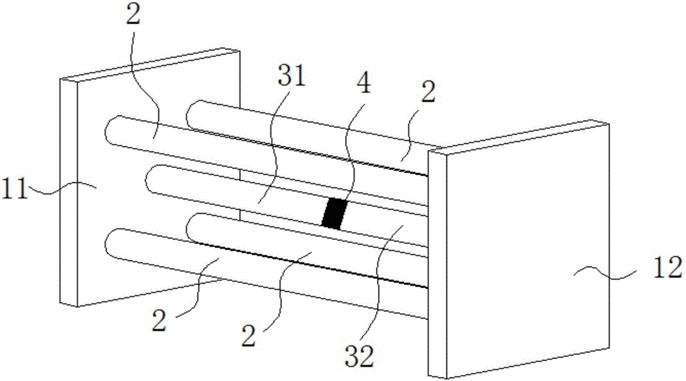
[0056] see figure 2 , an oil and gas pipeline restraint simulation device provided in this embodiment, including:
[0057] The first fixed plate 11 and the second fixed plate 12 arranged oppositely;
[0058] The rigid restraint bracket 2 is arranged between the first fixed plate 11 and the second fixed plate 12, and the axis of the rigid restraint bracket 2 is perpendicular to the opposite surfaces of the first fixed plate 11 and the second fixed plate 12;
[0059] The first sample tube 31, one end of which is arranged on the side opposite to the first fixed plate 11 and the second fixed plate 12;
[0060] The second sample pipe fitting 32, one end of which is arranged on the side of the second fixed plate 12 opposite to the first fixed plate 11;
[0061] The other end of the first sample pipe 31 is welded to the other end of the second sample pipe 32 to form a weld 4 .
[0062] The aforementioned oil and gas pipeline restraint simulation device is provided with a rigid re...
Embodiment 2
[0074] see Figure 7 , which is a flow chart of a simulation test method for restraint of oil and gas pipelines provided in this embodiment, which mainly includes the following steps:
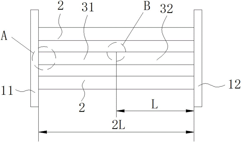
[0075] Step S100, setting the rigid restraint bracket. Between the first fixed plate 11 and the second fixed plate 12 arranged oppositely, a rigid restraint bracket 2 for connecting the first fixed plate 11 and the second fixed plate 12 is fixed, such as image 3 shown.
[0076] Step S200, welding the sample pipe fittings, respectively fixing one end of the first sample pipe fitting 31 and one end of the second sample pipe fitting 32 on the opposite side of the first fixing plate 11 and the second fixing plate 12; welding the first sample The other end of pipe fitting 31 and the other end of second sample pipe fitting 32 form weld seam 4, as figure 2 shown.
[0077] Step S300, test section cutting. Cutting at preset length positions on both sides of the weld 4 to obtain the test section 5...
PUM
 Abstract
Description
Claims
Application Information
 - R&D
- Intellectual Property
- Life Sciences
- Materials
- Tech Scout
- Unparalleled Data Quality
- Higher Quality Content
- 60% Fewer Hallucinations
Browse by: Latest US Patents, China's latest patents, Technical Efficacy Thesaurus, Application Domain, Technology Topic, Popular Technical Reports.
© 2025 PatSnap. All rights reserved.Legal|Privacy policy|Modern Slavery Act Transparency Statement|Sitemap|About US| Contact US: help@patsnap.com


