Cyclical ultrasonic impact process for maintaining welding joint
A technology for welding joints and maintenance, which is applied in the field of life extension of magnesium alloy welded structures, can solve the problems of low fatigue life of magnesium alloy welded structures, and achieve the effect of prolonging the service life
- Summary
- Abstract
- Description
- Claims
- Application Information
AI Technical Summary
Problems solved by technology
Method used
Image

Examples
Embodiment 1
[0036] (1) Grind the welding area and welding wire with fine sandpaper to fully remove the oxide film on the surface; clean the surface of the workpiece and welding wire with acetone to remove oil and dirt; then dry the surface of the workpiece and welding wire with a dry cotton cloth and let it stand.
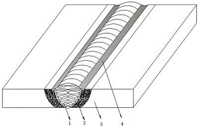
[0037] (2) The 8mm thick MB8 magnesium alloy plate is TIG welded with Φ3mm MB3 welding wire. The welding process parameters are shown in Table 2.
[0038] Table 2 welding process parameters
[0039]
[0040] (3) Choose a cylindrical impact head with a diameter of 3 mm and a semicircular head. The welding seam and the heat-affected area adopt double rows of impact heads with at least 4 needles, and the weld toe area adopts a single needle. Ultrasonic impact treatment is performed on the weld seam, weld toe and heat-affected zone of the welded joint. When impacting the weld toe, the impact gun reciprocates along the welding direction; when impacting the weld seam, the impa...
Embodiment 2
[0050] (4) Apply a tension-tension alternating fatigue load in the form of a sine wave of 55Mpa to the welded joint after impact, and the stress ratio R(σ min / σ max )=0.1, loading frequency f=110~115Hz, effect 0.5×0.763513×10 6 times (half of the post-weld impact fatigue life) to stop the load.
[0051] (5) Grind and clean the surface of the weld seam and the heat-affected zone with fine sandpaper to remove the scale and other dirt formed during use.
[0052] (6) Choose a cylindrical impact head with a diameter of 3 mm and a semicircular head. The welding seam and the heat-affected area adopt double rows of impact heads with at least 4 needles, and the weld toe area adopts a single needle. The impact speed is 15mm / min~20mm / min, and the number of reciprocating impacts is 4 times. Ultrasonic impact frequency is 18KHz. Excitation current: 1.0A.
[0053] (7) Implement ultrasonic impact treatment on the weld toe to make the transition between the base metal and the weld as s...
Embodiment 3
[0059] (4) Apply a tension-tension alternating fatigue load in the form of a sine wave of 60Mpa to the welded joint after impact, and the stress ratio R(σ min / σ max )=0.1, loading frequency f=110~115Hz, effect 0.5×0.437742×10 6 times (half of the post-weld impact fatigue life) to stop the load.
[0060] (5) Grind and clean the surface of the weld seam and the heat-affected zone with fine sandpaper to remove the scale and other dirt formed during use.
[0061] (6) Choose a cylindrical impact head with a diameter of 3 mm and a semicircular head. The welding seam and the heat-affected area adopt double rows of impact heads with at least 4 needles, and the weld toe area adopts a single needle. The impact speed is 15mm / min~20mm / min, and the number of reciprocating impacts is 4 times. Ultrasonic impact frequency is 18KHz. Excitation current: 1.0A.
[0062] (7) Implement ultrasonic impact treatment on the weld toe to make the transition between the base metal and the weld as s...
PUM
| Property | Measurement | Unit |
|---|---|---|
| Plate thickness | aaaaa | aaaaa |
| Plate thickness | aaaaa | aaaaa |
Abstract
Description
Claims
Application Information
 - R&D
- Intellectual Property
- Life Sciences
- Materials
- Tech Scout
- Unparalleled Data Quality
- Higher Quality Content
- 60% Fewer Hallucinations
Browse by: Latest US Patents, China's latest patents, Technical Efficacy Thesaurus, Application Domain, Technology Topic, Popular Technical Reports.
© 2025 PatSnap. All rights reserved.Legal|Privacy policy|Modern Slavery Act Transparency Statement|Sitemap|About US| Contact US: help@patsnap.com