Multi-hole culvert structure adopting foam concrete and corrugated steel sheets and construction method of multi-hole culvert structure

A technology of foam concrete and corrugated steel plate, which is applied in the field of culverts, can solve the problems of difficult compaction of fill, and achieve the effects of low foundation bearing capacity requirements, improved bearing capacity, and light weight

Active Publication Date: 2016-06-08
CHANGAN UNIV +1
View PDF10 Cites 11 Cited by
  • Summary
  • Abstract
  • Description
  • Claims
  • Application Information

AI Technical Summary

Problems solved by technology

The culvert structure has the advantages of light weight, low requirements on the bearing capacity of the foundation, strong a...

Method used


Image

  • Multi-hole culvert structure adopting foam concrete and corrugated steel sheets and construction method of multi-hole culvert structure
  • Multi-hole culvert structure adopting foam concrete and corrugated steel sheets and construction method of multi-hole culvert structure
  • Multi-hole culvert structure adopting foam concrete and corrugated steel sheets and construction method of multi-hole culvert structure

Examples


Embodiment 1

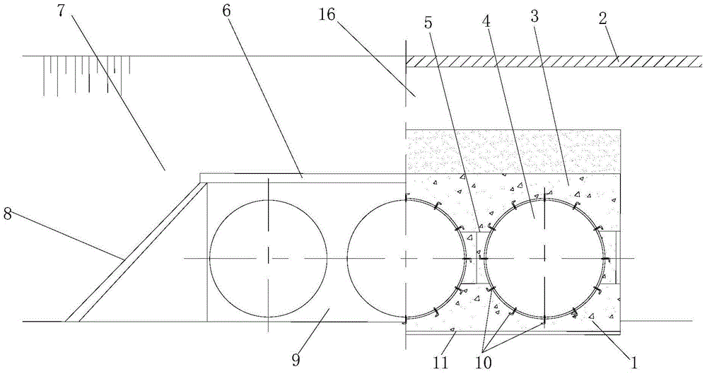
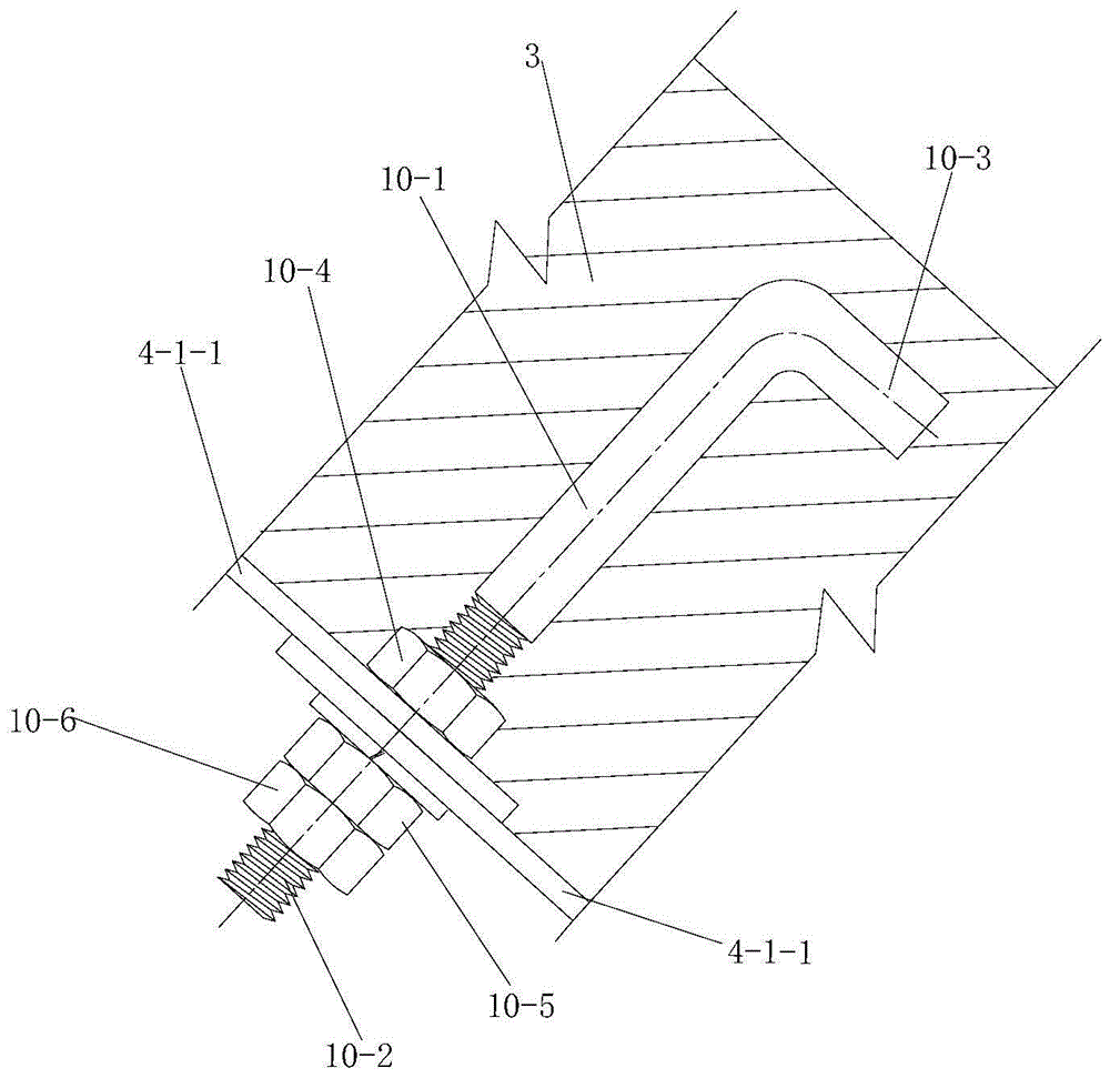
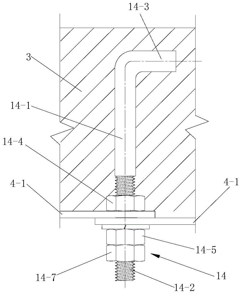
[0052] Such as figure 1 A porous culvert structure using foam concrete and corrugated steel plates is shown, including a culvert foundation 1, multiple water passing structures 4 assembled from corrugated steel plates, and filling bodies 3 located above and on both sides of the water passing structures 4 And the road surface 2 above the filling body 3; the water passing structure 4 includes a plurality of steel plate arch shell units 4-1 arranged along its water flow direction, and a plurality of steel plate arch shell units 4-1 are sequentially overlapped and connected, so The steel plate arch shell unit 4-1 is sequentially overlapped and connected by a plurality of single corrugated steel plates 4-1-1. The connecting pieces 10 are connected, and two adjacent steel plate arch shell units 4 - 1 are connected through the second connecting piece 14 passing through their overlapping parts.

[0053] In this embodiment, the foamed concrete and the corrugated steel plate are used i...

Embodiment 2

[0074] Such as Figure 5 As shown, the difference between the culvert structure of this embodiment and the culvert structure of Embodiment 1 is that: the culvert foundation 1 and the filling body 3 are all made of foam concrete layered pouring, and the culvert foundation 1 and the filling body 3 The second reinforcing steel mesh 12 is uniformly arranged between and between two adjacent layers of filling bodies 3 .

[0075] In view of the insufficient bearing capacity of the foundation and the small filling height of the culvert subgrade, which may lead to uneven settlement in the culvert-subgrade transition section along the driving direction after construction, this embodiment adopts pouring foam concrete for the weak foundation and culvert. The side roadbed is filled with soil, and the steel plate arch shell is assembled on the poured foam concrete foundation, and the foam concrete is poured on both sides and the top of the steel plate arch shell.

[0076] In this embodimen...

Embodiment 3

[0080] Such as Figure 6 As shown, the difference between the culvert structure of this embodiment and the culvert structure of Embodiment 1 is that the water passing structure 4 is an arch culvert. The arch culvert is a double or porous corrugated steel arch culvert with large aperture.

[0081] In this embodiment, a plurality of arch ribs 13 are arranged on the side wall of the water passing structure 4 close to the filling body 3 , and the plurality of arch ribs 13 are arranged at intervals along the water flow direction of the water passing structure 4 . By setting the arch ribs 13, the rigidity of the side wall of the water passing structure 4 is effectively enhanced.

[0082] In addition, the difference between the construction method of the culvert structure of this embodiment and the construction method of the culvert structure of Embodiment 1 is that: the culvert foundation 1 includes the left foundation of the culvert and the right foundation of the culvert; a plura...


PUM


Abstract

The invention discloses a multi-hole culvert structure adopting foam concrete and corrugated steel sheets. The multi-hole culvert structure comprises an arch shell formed by assembling corrugated steel materials and foam concrete arranged around the arch shell in a filling mode. Water passing structures comprise multiple steel sheet arch shell units. The steel sheet arch shell units are formed by assembling multiple single corrugated steel sheets. Every two adjacent single corrugated steel sheets are connected through a first connecting part which penetrates through a lap joint part between the every two adjacent single corrugated steel sheets. Every two adjacent steel sheet arch shell units are connected through a second connecting part which penetrates through a lap joint part between the every two adjacent steel sheet arch shell units. The multi-hole culvert structure has the advantages of being small in weight, low in requirement for foundation bearing capacity, high in adaptability to foundation deformation, good in mechanical stability and the like. The invention further discloses a culvert structure construction method. The culvert structure construction method includes the following steps of culvert foundation construction, water passing structure construction, filling body construction and road surface construction. By means of the method, the problem that traditional backfill materials such as gravels on top and the two sides of the water passing structures are difficult to tightly compact is effectively solved, and the unfavorable influence of the compaction process on the stability and the side walls of the water passing structures is eliminated.

Description

technical field [0001] The invention belongs to the technical field of culverts, in particular to a porous culvert structure using foam concrete and corrugated steel plates and a construction method thereof. Background technique [0002] In domestic highway and railway construction, culverts occupy a large proportion. At present, most culverts are designed with reinforced concrete or masonry structures. The culvert has a large amount of masonry, cumbersome construction and long construction period. Under complex geological conditions, foundation treatment and foundation engineering account for a large amount of work, making construction difficult. Due to the poor ability of some structures to adapt to the deformation of the foundation, when the foundation deforms unevenly, it will cause cracking of the concrete structure and leakage of deformation joints, which will affect the function and life of the culvert, and seriously affect the bearing capacity of the subgrade and t...

Claims


Application Information

Patent Timeline
IPC IPC(8): E01F5/00E02D27/32
CPCE01F5/005E02D27/32
Inventor 原喜忠王立鹏欧阳煜
Owner CHANGAN UNIV
Why Eureka
Try Eureka