
Roadway sidewall intercepting type mine cooling method and system

A roadway closure and mine technology, which is applied to drilling equipment and methods, mine/tunnel ventilation, drilling equipment, etc., can solve the problems of high investment and operation costs, low heat transfer coefficient, high compressive strength, etc.

Active Publication Date: 2016-06-08
HENAN POLYTECHNIC UNIV
View PDF8 Cites 7 Cited by
  • Summary
  • Abstract
  • Description
  • Claims
  • Application Information

AI Technical Summary

Problems solved by technology

[0005] For example: Most of the ventilation and cooling uses refrigeration units or refrigerants to cool the intake air flow. Although it has a certain effect, due to the large air flow in the mine and cannot be recycled, the investment and operation costs are too large, and the cooling effect is limited.
[0006] The cooling method of laying heat insulation materials on the roadway wall is to add heat insulation materials to the back support of the roadway or the filling behind the wall, so as to "shield" the heat radiation of the surrounding rock of the roadway wall to the working face from the roadway, so as to reduce the temperature of the roadway. If the surrounding rock pressure is too high, the thermal insulation material should have the characteristics of high compressive strength, low heat transfer coefficient, and small bulk density, so that the materials used are expensive; in addition, this technology is only temporarily delayed. The heat transfer from the surrounding rock to the roadway does not prevent the heat transfer from the surrounding rock to the roadway

Method used


Image

  • Roadway sidewall intercepting type mine cooling method and system
  • Roadway sidewall intercepting type mine cooling method and system
  • Roadway sidewall intercepting type mine cooling method and system

Examples


Embodiment Construction

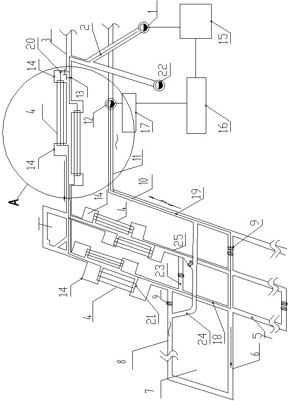
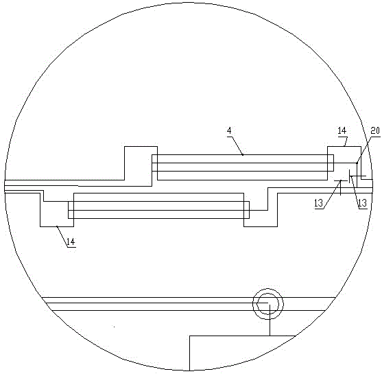
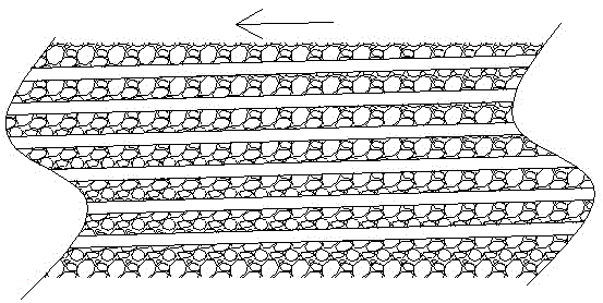
[0036] figure 1 Shown is the roadside closure type mine cooling system for realizing the roadside closure type mine cooling method of the present invention. figure 1 and image 3 The arrows in each place indicate the direction of wind flow at this place. In the present invention, the direction of water flow is taken as the forward direction. Transporting up and down the hill 5 shows that the corresponding structure in the accompanying drawings can be transported up the hill, and can be transported down the hill again. Track up and down hill 25 represents that the corresponding structure in the accompanying drawing can be track up hill, can be track down hill again.

[0037] The invention discloses a cooling method for roadside interception mines, referring to figure 1 , figure 2 and image 3 , the air inlet alley 3 both sides of the mine that uses this method is provided with drill field 14 at intervals, and the air inlet alley is connected with transportation up and do...


PUM

PropertyMeasurementUnit
Diameteraaaaaaaaaa

Abstract

The invention discloses a roadway sidewall intercepting type mine cooling method and a cooling system. Two sides of an intake main roadway of a mine using the method are provided with drill sites in a spaced manner, two sides of a track uphill and downhill and a transport uphill and downhill are provided with drill sites in a spaced manner, and directional boreholes are constructed in two ends of each drill site; the method comprises: first, preparing cooling water with a refrigerating unit and delivering the cooling water into the intake main roadway; second, enabling the cooling water to flow through the directional boreholes between the adjacent drill sites on two sides of the intake main roadway; third, allowing high-temperature water to flow to a return air shaft; fifth, after a surface pump station pumps water to the surface, sending the water to a heat exchanger, re-delivering the water cooled by the heat exchanger into the refrigerating unit, and enable a nonstop cycle from the first step. The invention also discloses the cooling system implementing the above-mentioned method. The method and system of the invention are good in cooling effect, can adjust water flow for each water injection point and can make effective use of terrestrial heat.

Description

technical field [0001] The invention relates to the technical field of underground temperature reduction, is suitable for high-temperature mines with strong geothermal heat, and in particular relates to a mine cooling method and a cooling system. Background technique [0002] With the increase of mine mining intensity and the extension of mining depth, geothermal (geothermal heat source) disasters gradually threaten mine production, and the number of high-temperature mines is also increasing. Following the five major disasters in mines, geothermal has gradually become a major disaster in coal mine production safety. [0003] Mine ventilation can not only supply underground fresh air, dilute gun smoke, gas and other toxic and harmful gases, but also effectively remove heat from the mining face, maintain a comfortable working environment, and ensure the physical health and labor safety of underground workers. The mining face must have sufficient air volume, but the adjustment...

Claims


Application Information

Patent Timeline
IPC IPC(8): E21F3/00E21B7/04
CPCE21B7/046E21F3/00
Inventor 魏建平李波刘勇尚显光徐向宇张宏图秦恒洁贾炳
Owner HENAN POLYTECHNIC UNIV
Learn More