Pressure expander of centrifugal compressor

A centrifugal compressor and diffuser technology, which is applied in the direction of machine/engine, mechanical equipment, engine manufacturing, etc., can solve the problems of large airflow angle of attack and enlarge the working range, so as to increase the flow rate, improve the incident airflow angle, prevent The effect of surge

Active Publication Date: 2016-06-08
嘉兴芸诗娇电子商务有限公司
View PDF7 Cites 22 Cited by
  • Summary
  • Abstract
  • Description
  • Claims
  • Application Information

AI Technical Summary

Problems solved by technology

[0006] The object of the present invention is to provide a diffuser for a centrifugal compressor in order to solve the problem that the air flow angle at the inlet of the diffuser is too large under the condition of small flow. The direction of the guided airflow changes, changing the angular distribution of the airflow in the diffuser channel, enabling more airflow to flow along the airflow surface, and inhibiting the occurrence of airflow separation on the blade surface, which not only improves the working efficiency of the diffuser, but also increases Wider range of work

Method used


Image

  • Pressure expander of centrifugal compressor
  • Pressure expander of centrifugal compressor
  • Pressure expander of centrifugal compressor

Examples


Embodiment Construction

[0023] The present invention will be further described below in conjunction with the accompanying drawings and embodiments.

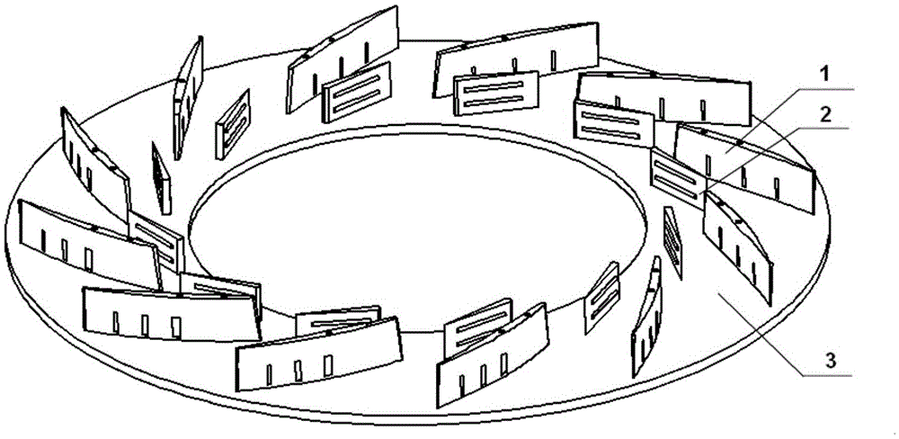
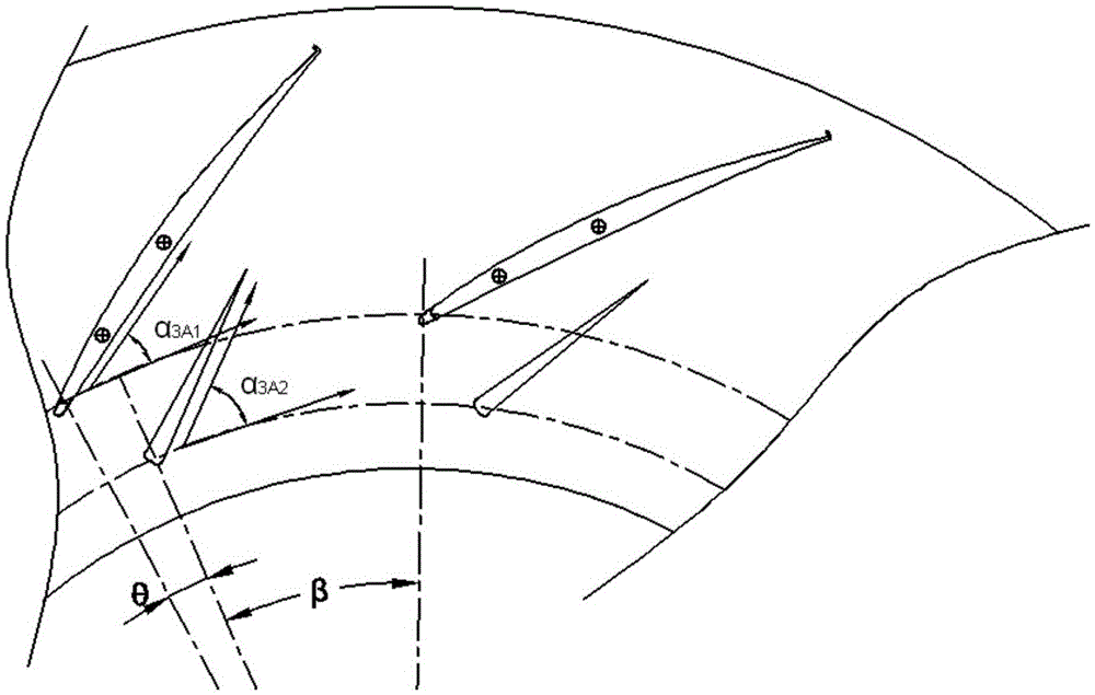
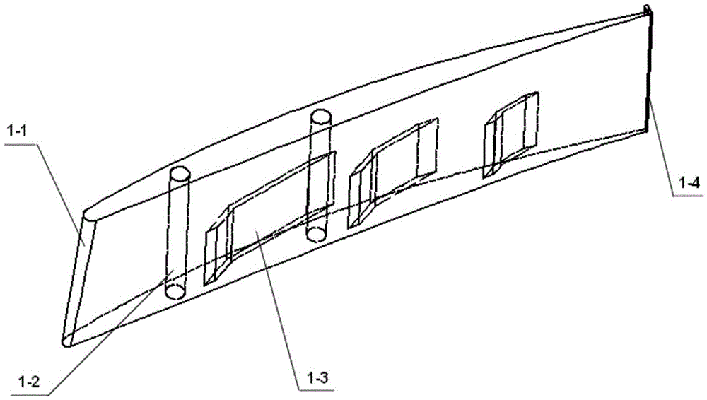
[0024] Such as figure 1 and 2 As shown, the diffuser of the centrifugal compressor includes long blades 1, short blades 2, disc 3 and wheel cover; there are 12 long blades 1, which are evenly distributed on the disc along the circumferential direction; two adjacent long blades 1 A short blade 2 is arranged in the flow channel, and the short blade 2 is close to the side of the suction surface of the long blade 1 . On the same cross-section, the radius of the circle centered on the center of the disc where the intercept point of the leading edge line of the suction surface of the short blade 2 is 15mm smaller than the radius of the circle where the intercept point of the leading edge line of the suction surface of the long blade 1 is located, and the suction surface of the short blade 2 The central angles between the intercept points of the leading edge...


PUM


Abstract

The invention discloses a pressure expander of a centrifugal compressor. The structure of the pressure expander is improved, and high application value is achieved for further improving working performance of the pressure expander. A short blade is arranged in runners of every two adjacent long blades; the front edges of the long blades are curved surfaces and are arranged obliquely, and the included angles between front edge lines and the central axis of a wheel disc are 6 degrees to 8 degrees; the radius of curvature of the front edges of the long blades is gradually increased from the wheel disc to a wheel cover; each long blade is provided with three broken-line-shaped channels penetrating through a corresponding pressure surface and a corresponding suction surface; tail edge wing tips are arranged on the portions, located on the pressure surfaces, of the rear edges of the long blades. Occurrence of separation of airflow on the surfaces of the blades is restrained through the short blades in the runners of the adjacent long blades; the pressure differences between the pressure surfaces and the suction surfaces are reduced through the broken-line-shaped channels, the adverse pressure gradient is reduced, and separate airflow on boundary layers of the suction surfaces at the tails of part of the blades is effectively blown away; increase of wing tip vortexes generated by the pressure differences between the suction surfaces and the pressure surfaces on the rear edges of traditional wing-type blades can be restrained through parabola-shaped winglets on the tail edges.

Description

technical field [0001] The invention belongs to the field of ventilation equipment, and relates to a centrifugal fan, in particular to a diffuser of a centrifugal compressor. Background technique [0002] As an energy conversion device, the centrifugal compressor mainly drives the movement of the gas in the impeller channel through the rotation of the impeller, and converts the mechanical energy of the prime mover into the energy of the gas. Due to its high pressure, wide range of stable working conditions, simple structure, and easy maintenance, centrifugal compressors are widely used in industries such as petroleum, aerospace, metallurgy, chemicals, and mines, and play an important role. [0003] In centrifugal compressors, the diffuser is generally divided into two types: vaneless diffuser and bladed diffuser. The vaneless diffuser is usually composed of two flat walls forming an annular channel. The structure of the vaneless diffuser is simple, the cost is low, the per...

Claims


Application Information

Patent Timeline
Patent Type & Authority Applications(China)
IPC IPC(8): F04D29/46F04D29/66
CPCF04D29/464F04D29/663F05D2250/52F04D29/444
Inventor 窦华书陈兴魏义坤陈小平杨徽
Owner 嘉兴芸诗娇电子商务有限公司
Why Eureka
Try Eureka