Bearing-free permanent magnetic synchronous generator

A permanent magnet synchronous and generator technology, applied in synchronous machines, synchronous machine parts, magnetic circuits, etc., can solve the problems of reducing dynamic performance, increasing costs, and difficulty in generators, reducing mechanical noise and improving reliability. Effect

Active Publication Date: 2016-06-08
扬中市冠捷科创有限公司
View PDF7 Cites 15 Cited by
  • Summary
  • Abstract
  • Description
  • Claims
  • Application Information

AI Technical Summary

Problems solved by technology

It is difficult for generators to maintain constant voltage. For occasions with high stability requirements, methods such as voltage regulation by power electronic converters, double-rotor or double-stator voltage regulation must be used, which will increase costs and reduce dynamic performance.

Method used


Image

  • Bearing-free permanent magnetic synchronous generator
  • Bearing-free permanent magnetic synchronous generator
  • Bearing-free permanent magnetic synchronous generator

Examples


Embodiment Construction

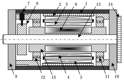
[0021] see figure 1 , the present invention comprises casing 1, stator core 2, permanent magnet rotor and rotating shaft 13, outermost is casing 1, and the axial left end of casing 1 is fixed left end cap 9, and axial right end is fixed right end cap 10. A rotating shaft 13 is installed at the center of the casing 1 , and the rotating shaft 13 is coaxially connected with the casing 1 . There is a stator core 2 and a permanent magnet rotor inside the casing 1, the stator core 2 is fixedly connected to the inner wall of the casing 1, the permanent magnet rotor is coaxially sleeved outside the rotating shaft 13, and the stator core 2 is coaxially sleeved outside the permanent magnet rotor, which belongs to the outer stator Inner rotor structure. There is a radial air gap between the stator core 2 and the permanent magnet rotor. The permanent magnet rotor is composed of permanent magnets 6 and fastening connectors 15 , and the permanent magnets 6 are radially magnetized and surf...


PUM


Abstract

The invention discloses a bearing-free permanent magnetic synchronous generator. A permanent magnetic rotor is coaxially sleeved with a stator iron core, the stator iron core is evenly provided with 36 stator grooves in the circumferential direction, and each stator groove is internally provided with an inner layer winding and an outer layer winding. Each outer layer winding is composed of two pairs of pole generation windings, the number of stator grooves of each pole and each phase is three, and each inner layer winding is a pair of pole suspension force windings and two pairs of pole excitation windings. The generation windings are distributed according to an A1+ phase, a B1- phase, a C1+ phase, an A1- phase, a B1+ phase, a C1- phase, an A2+ phase, a B2- phase, a C2+ phase, an A2- phase, a B2+ phase and a C2- phase in the clockwise direction. The suspension force windings are distributed according to an a+ phase, a b- phase, a c+ phase, an a- phase, a b+ phase and a c- phase in the clockwise direction. The excitation windings are distributed according to an X1+ phase, a Y1- phase, a Z1+ phase, an X1- phase, a Y1+ phase, a Z1- phase, an X2+ phase, a Y2- phase, a Z2+ phase, an X2- phase, a Y2+ phase and a Z2- phase in the clockwise direction. Operation reliability of a motor under special working conditions is improved.

Description

technical field [0001] The invention relates to the field of permanent magnet synchronous generators and bearingless motors, in particular to a bearingless permanent magnet synchronous generator used under the special working conditions of prime mover driving speed changes and external circuit load changes. Background technique [0002] The permanent magnet synchronous generator has many advantages such as simple structure, high efficiency, high power density, flexible topological structure, no need for brush structure, reliable operation, etc. The application of energy storage system electric generator integrated machine and many other occasions is becoming more and more extensive, which puts forward higher requirements for the reliability of generator operation. Due to the complex and changeable working environment of the generator, it is easy to cause a series of electrical or mechanical failures of its stator, rotor, bearing and other components, and the failure rate of ...

Claims


Application Information

Patent Timeline
Patent Type & Authority Applications(China)
IPC IPC(8): H02K21/02H02K1/16H02K3/12H02K3/28H02K13/00
CPCH02K1/16H02K3/12H02K3/28H02K13/00H02K21/029H02K2201/15H02K2203/03H02K2213/03
Inventor 朱熀秋胡亚民李慧郝正杰陈颖郁叶刘浩蒋莉
Owner 扬中市冠捷科创有限公司
Why Eureka
Try Eureka