A Flat Linear Motor Servo Actuator Suitable for Flat Installation Space

A servo actuator and installation space technology, applied in the direction of electric components, electrical components, electromechanical devices, etc., can solve the problems of elastic deformation of mechanical components, non-linear errors, limiting the performance of servo systems, etc., to achieve compact connection and good manufacturability , the effect of reasonable layout

Active Publication Date: 2014-04-02
CHINA ACAD OF LAUNCH VEHICLE TECH +1
View PDF0 Cites 5 Cited by
  • Summary
  • Abstract
  • Description
  • Claims
  • Application Information

AI Technical Summary

Problems solved by technology

The existing aerospace electric servo mechanism, the driving mechanism of the center of mass adopts a rotating motor, which needs to be converted into a l

Method used


Image

  • A Flat Linear Motor Servo Actuator Suitable for Flat Installation Space
  • A Flat Linear Motor Servo Actuator Suitable for Flat Installation Space

Examples


Embodiment 1

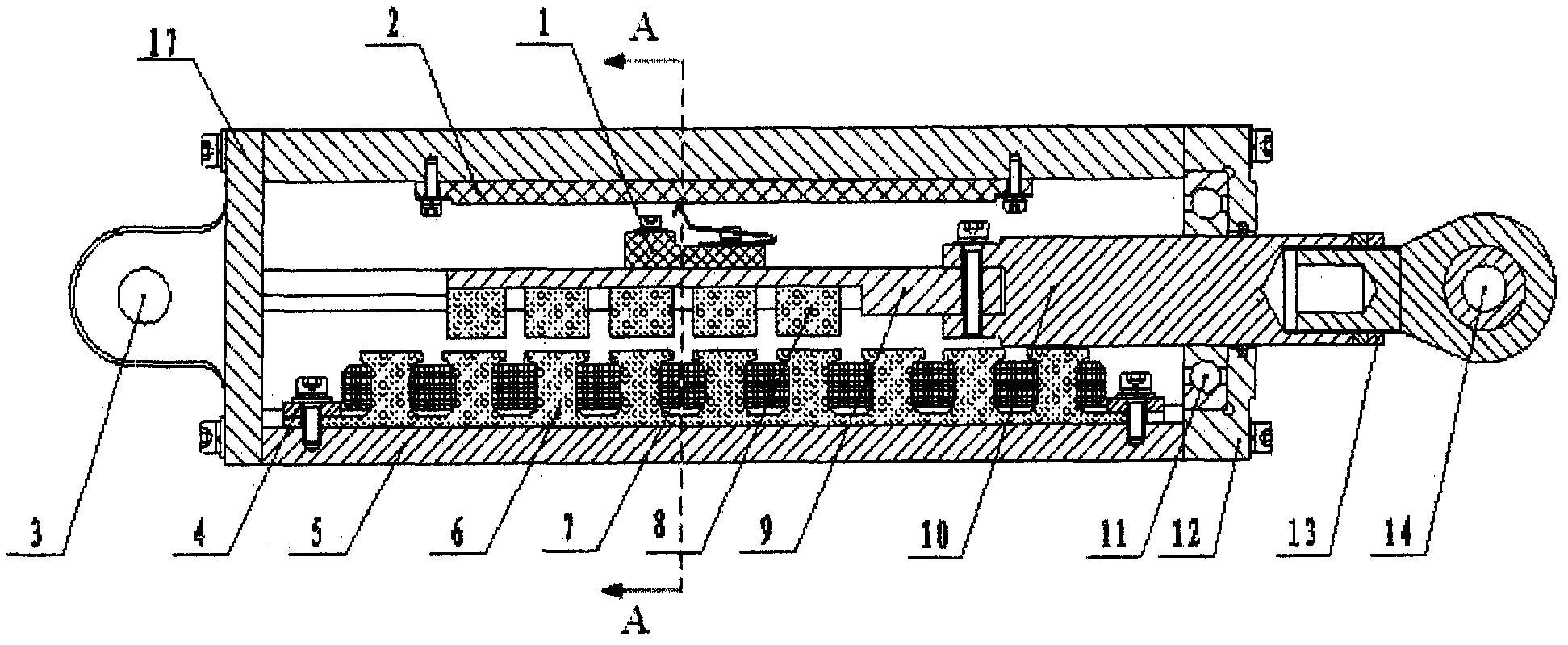
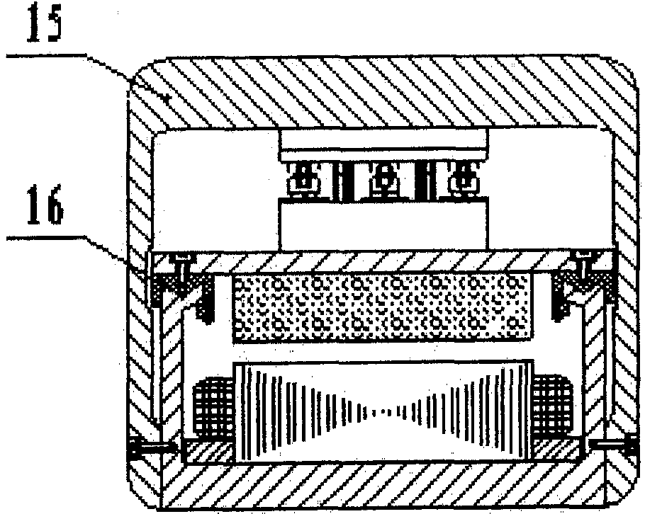
[0024] The present invention is a flat linear motor servo actuator suitable for flat installation space, comprising an actuator base 5, an actuator housing 15, a front end cover 12, a rear end cover 17, a stator core 6 wound on a stator iron The coil winding 7 on the core 6, the guide rail assembly 16; the actuator base 5 is provided with a rectangular groove, which is a cross-section Shaped and longitudinally extending flat structure, a total of 9 stator cores 6 are fixed longitudinally and parallel to the bottom wall of the groove of the actuator base 5 by screws, and the coil winding 7 is three-phase wiring winding the 9 stator cores 6 structure; the actuator housing 15 is provided with a rectangular groove, which is an inverted cross-section Shaped and longitudinally extending flat structure; the actuator housing 15 is covered on the actuator base 5, and the actuator housing 15 is connected to the actuator base 5 by screws on the lateral side walls of the actuator housin...

Embodiment 2

[0029] The difference between this embodiment and Embodiment 1 is that the nine stator cores 6 are formed by stamping, and the nine parallel stator cores 6 that are punched out adopt an integral connection structure at the bottom. The stamped bottom integrally connected stator core 6 is provided with two bead 4 at both ends in the longitudinal direction, and the bead 4 fixes the bottom integrally connected stator core 6 and the actuator base 5 by screws.

[0030] During work, the rear lug assembly 3 is fixed to a static object, and the bolt head assembly 14 is connected to medium and small power loads such as driving the seeker antenna or changing the center of mass of the warhead. The linear motor is supplied with direct current, and the motor generates electromagnetic torque to drive the secondary mover body 9 to perform linear motion, and then drive the guide column 10 to perform linear motion. The linear position and speed of the motor are detected by the linear displaceme...


PUM


Abstract

The invention relates to an electric servo mechanism, in particular to a flat linear motor servo actuator suitable for flat installation spaces. Including the actuator base, the actuator housing covered on the actuator base, the front end cover and the rear end cover fixed on both ends of the actuator base and the actuator housing, and several stator irons fixed on the actuator base. Core, the coil winding wound on the stator core, also includes the guide rail assembly fixed on both sides of the actuator base, the mover body slidably connected to the guide rail assembly, and several magnetic steels fixed on the lower surface of the mover body; The steel is located directly above the stator core and coil windings; one end of the mover body is connected to a guide column, and the other end of the guide post passes through the front end cover and is connected to a bolt head assembly; the upper surface of the mover body and the inner wall of the actuator shell are provided with a Linear displacement sensor. The invention has high transmission efficiency, dynamic response, resolution and reliability, is suitable for flat installation space, and can drive seeker antennas or change warhead centroids and other small and medium power loads.

Description

technical field [0001] The invention relates to a linear electric servo mechanism, in particular to a flat linear motor servo actuator suitable for a flat installation space. Background technique [0002] In the missile weapon system, the center of mass adjustment system is often used to change the inertia of the missile by adjusting the center of mass, which is beneficial to the attitude adjustment of the missile. In the existing aerospace electric servo mechanism, the drive mechanism of the center of mass adopts a rotating motor, which needs to be converted into a linear motion through a reduction mechanism and a ball screw. The elastic deformation, friction, gap, nonlinearity and Errors and other issues limit the further improvement of the performance of the servo system. Therefore, it is urgent to use a linear motor servo actuator to directly drive the centroid load, which can save the motion conversion link, greatly simplify the servo structure, and further improve the...

Claims


Application Information

Patent Timeline
IPC IPC(8): H02K41/035H02K16/00H02K5/04
Inventor 韩继文黄玉平侍威王春明胡宝军郑继贵
Owner CHINA ACAD OF LAUNCH VEHICLE TECH
Why Eureka
Try Eureka