Board drawing forming device and method based on electrorheological fluid

A technology of electrorheological fluid and sheet metal, which is applied in the field of sheet metal deep drawing and forming devices based on electrorheological fluid, and in the field of sheet metal deep drawing and forming devices, which can solve problems such as increased cleaning process, poor force transmission effect, and difficult sealing

Active Publication Date: 2016-06-15
HARBIN UNIV OF SCI & TECH
View PDF8 Cites 26 Cited by
  • Summary
  • Abstract
  • Description
  • Claims
  • Application Information

AI Technical Summary

Problems solved by technology

[0007] The purpose of the present invention is to provide a cur

Method used


Image

  • Board drawing forming device and method based on electrorheological fluid
  • Board drawing forming device and method based on electrorheological fluid

Examples


specific Embodiment approach 1

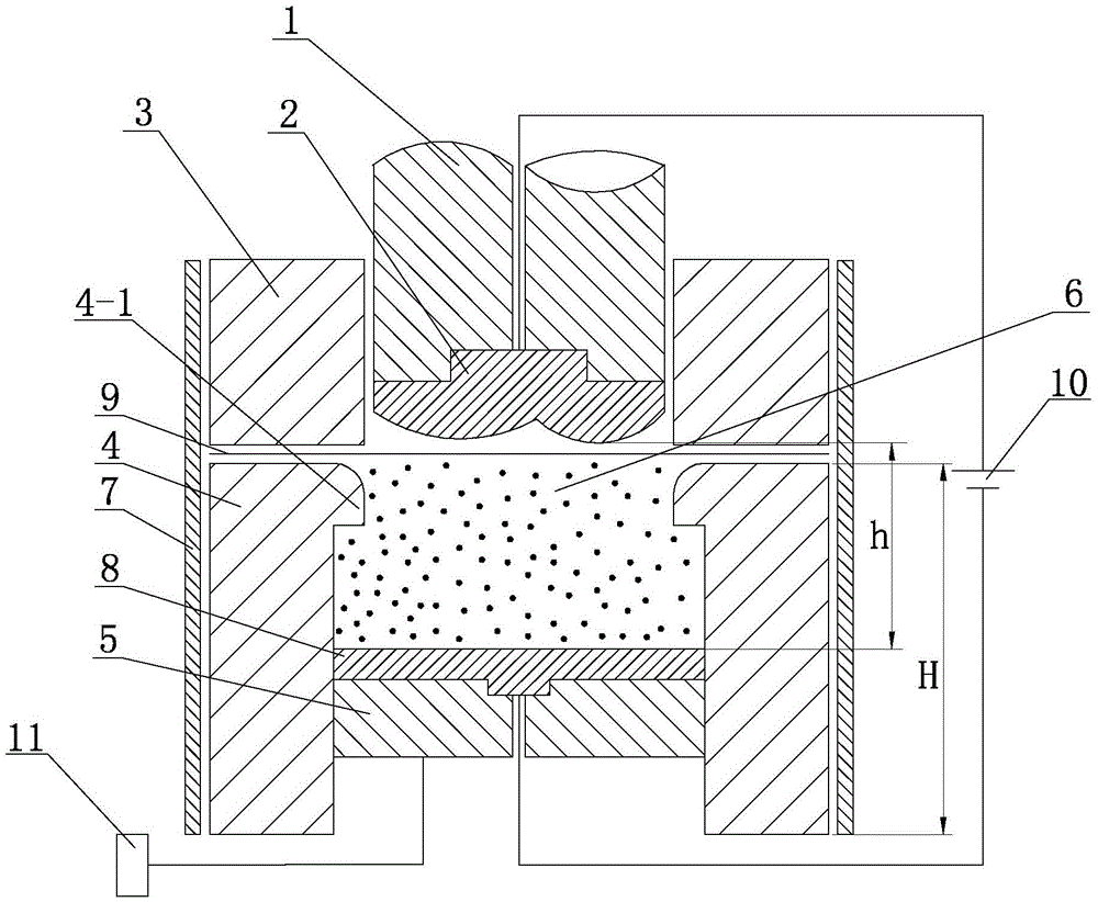
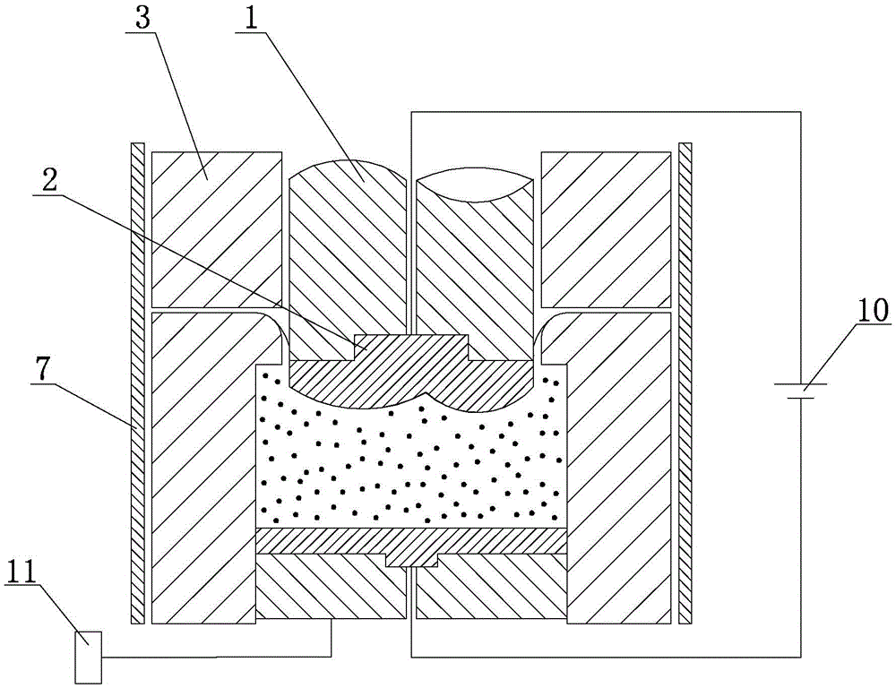
[0031] Specific implementation mode one: combine figure 1 Describe this embodiment, this embodiment includes punch seat 1, punch terminal 2, blank holder 3, die 4, plunger 5, insulating layer 7, electrode plate 8, power supply control unit 10 and plunger control unit 11 , the blank holder 3 and the die 4 are set up and down, the punch terminal 2 and the punch seat 1 are arranged in the inner hole of the blank holder 3 from bottom to top, and the plunger 5 and the electrode plate 8 are arranged in the concave from bottom to top. In the inner hole of the mold 4, the concave mold 4 and the electrode plate 8 form a closed liquid chamber cavity 6 for containing the electrorheological fluid, and the punch terminal 2 can pass through the blank holder 3 to drive the sheet material 9 down into the liquid chamber cavity 6, the upper entrance of the die 4 is provided with a flange 4-1, the diameter of the flange 4-1 is smaller than the diameter of the plunger 5, and the insulating layer ...

specific Embodiment approach 2

[0032] Specific implementation mode two: combination figure 1 Describe this embodiment, the material of the punch base 1, blank holder 3, die 4 and insulating layer 7 of this embodiment is an insulating material, and the insulating material is polytetrafluoroethylene, pottery, plexiglass or epoxy resin; Insulation and high pressure resistance, high strength and hardness, not easy to deform, etc. Other connection relationships are the same as those in the first embodiment.

specific Embodiment approach 3

[0033] Specific implementation mode three: combination figure 1 To illustrate this embodiment, the materials of the punch terminal 2 and the electrode plate 8 in this embodiment are metal, oxide, conductive polymer or porous carbon material; they are required to be electrically conductive, have high strength and hardness, and are not easily deformed. Other connections are the same as those in the first or second specific embodiment.


PUM


Abstract

The invention discloses a board drawing forming device and method based on electrorheological fluid. The device comprises a closed fluid chamber cavity formed by a female die and a plate electrode; a male die terminal and a positive electrode of a power source control unit are electrically connected; the plate electrode and a negative electrode of the power source control unit are electrically connected; and a plunger is connected with a plunger control unit. The method comprises the steps that 1, the electrorheological fluid of the required proportion of components is prepared; 2, the initial position of the working end face of the plate electrode is set; 3, the electrorheological fluid prepared in the first step is injected into the fluid chamber cavity; 4, a board is put on the upper end face of the female die; 5, a blank holder is downwards moved to the board; 6, the power source control unit controls the intensity of an electric field, and the plunger control unit makes the plate electrode to generate constant acting force on the electrorheological fluid; 7, the male die terminal moves downwards to drive the board for drawing forming; 8, the plunger, the plate electrode, the male die terminal and a male die base retreat and withdraw synchronously; and 9, the male die base and the male die terminal are removed, and the electric field of a working area is unloaded through the power control unit. The board drawing forming device and method based on the electrorheological fluid are used for board drawing forming.

Description

technical field [0001] The invention relates to a plate deep drawing forming device and method, in particular to a plate deep drawing forming device and method based on electrorheological fluid, and belongs to the technical field of plate flexible medium forming. Background technique [0002] Sheet flexible medium forming refers to the use of liquid water or oil, viscous medium and solid particles as force transmission media to shape the sheet. With the rapid development of aerospace, automobile manufacturing and other fields, the requirements for parts in terms of light weight, high precision, and low consumption have also increased. Sheet metal flexible medium forming is a method that has gradually developed in response to this demand. an advanced manufacturing technology. However, due to the limitations of the process itself, bottlenecks such as difficult sealing, need for cleaning or poor force transmission effect restrict the promotion and application of traditional me...

Claims


Application Information

Patent Timeline
IPC IPC(8): B21D22/22B21D26/021B21D26/031
CPCB21D22/22B21D26/021B21D26/031
Inventor 李峰周福见金成闯
Owner HARBIN UNIV OF SCI & TECH
Why Eureka
Try Eureka