
Quick-cooling device for fiber yarn pipelines

A fiber filament and pipeline technology, which is applied in the field of fiber filament pipeline rapid cooling device, can solve the problems of reducing the surface temperature of the pipeline, time-consuming and laborious, and poor cooling effect.

Inactive Publication Date: 2016-06-15
JIANGSU ZHONGSHI FIBER CO LTD
View PDF0 Cites 7 Cited by
  • Summary
  • Abstract
  • Description
  • Claims
  • Application Information

AI Technical Summary

Problems solved by technology

[0002] The fiber yarn has a high temperature after being extruded by the extruder, and the fiber yarn pipeline needs to be cooled. The current cooling method adopts separate cooling or water cooling, and the air cooling time is long, the cooling effect is not good, time-consuming and laborious, and the production efficiency is not high; Water cooling is to immerse the pipe in water, thereby reducing the temperature of the pipe surface. Due to the continuous heat generated inside the pipe, the water temperature rises over time, and the heat needs to be dissipated before processing, which will affect the work progress and bring troubles to the production of enterprises. caused great inconvenience

Method used


Image

  • Quick-cooling device for fiber yarn pipelines
  • Quick-cooling device for fiber yarn pipelines

Examples


Embodiment Construction

[0016] The present invention will be further clarified below in conjunction with the drawings and specific embodiments. It should be understood that the following specific embodiments are only used to illustrate the present invention and not to limit the scope of the present invention. It should be noted that the words "front", "rear", "left", "right", "upper" and "lower" used in the following description refer to the directions in the drawings, and the words "inner" and "outer" "Respectively refers to the direction toward or away from the geometric center of a particular component.

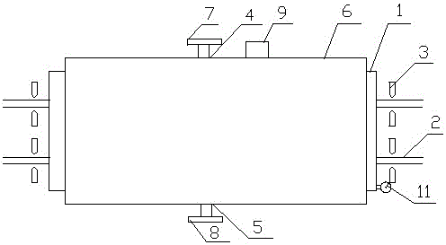
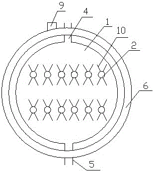
[0017] As shown in the figure, the fiber pipe rapid cooling device of the present invention includes a horizontal cooling box 1, a fiber channel 2, a tuyere 3, a water inlet pipe 4, a water outlet pipe 5, and a heat dissipation box 6. The cooling box 1 is a cylindrical structure, the fiber channel 2 passes through the two ends of the cooling box 1, the air nozzle 1 is arranged at both ends of the co...


PUM


Abstract

The invention discloses a quick-cooling device for fiber yarn pipelines. The quick-cooling device comprises a horizontal cooking box, fiber channels, air nozzles, a water inlet pipe, a water outlet pipe and a radiating box, wherein the cooling box adopts a cylinder structure; the fiber channels penetrate through two ends of the cooling box; the air nozzles are arranged at the two ends of the radiating box, and are aligned with the fiber channels; the water inlet pipe is arranged at the upper part of the side surface of the cooling box; the water outlet pipe is arranged at the lower part of the side surface of the cooling box; the radiating box is arranged outside the cooling box; a three-way valve I is arranged at the connection part between the water inlet pipe and the radiating box; a three-way valve II is arranged at the connection part between the water outlet pipe and the radiating box; a water pump is arranged on the radiating box; V-shaped radiating fins are arranged on the surfaces of the fiber channels inside the cooling box. The combined action of air cooling and water cooling is adopted, so that the cooling time is short; the radiating box is arranged outside the cooling box, and the radiating fins are arranged outside the fiber channels, so that the radiating area is increased, the radiating speed is high, and the radiating effect is good.

Description

Technical field [0001] The invention belongs to the technical field of fiber filament processing equipment, and specifically relates to a fiber filament pipeline rapid cooling device. Background technique [0002] After the fiber filament is extruded by the extruder, it has a higher temperature, and the fiber filament pipe needs to be cooled. The current cooling method adopts separate cooling or water cooling, which has a long air cooling time, poor cooling effect, time-consuming and labor-intensive, and low production efficiency; Water cooling is to make the pipeline immersed in water, thereby reducing the temperature of the pipeline surface. This kind of device continuously produces heat inside the pipeline, and the water temperature rises over time. The heat needs to be dissipated before treatment, which affects the work progress and gives the enterprise production Brought great inconvenience. Summary of the invention [0003] In order to solve the above-mentioned problems, th...

Claims


Application Information

Patent Timeline
IPC IPC(8): B29C47/86B29L7/00
CPCB29C48/87B29C48/05B29L2007/00
Inventor 董树兵杨爱明张石青罗巧干
Owner JIANGSU ZHONGSHI FIBER CO LTD
Learn More