
Composite energy field heating method

A composite energy field and heating method technology, applied in the field of heating, can solve the problems of small temperature difference, poor control of heating and curing conditions, and great distances, etc., to reduce the scrap rate, solve the problem of collaborative manufacturing of shape and property, and reduce layered effect

Active Publication Date: 2016-06-15
CENT SOUTH UNIV
View PDF8 Cites 20 Cited by
  • Summary
  • Abstract
  • Description
  • Claims
  • Application Information

AI Technical Summary

Problems solved by technology

[0007] However, when using these above-mentioned devices or methods to heat and cure composite materials in a composite energy field, that is, to use microwave methods and traditional methods (autoclave) to heat and cure composite materials at the same time, the heating and curing conditions cannot be well controlled. The actual result of the composite energy field heating and curing of the composite material is far from the ideal value and design value
How to make the internal temperature field of large-scale thick parts and large-scale variable-thickness parts uniform? At present, there is no method that can quickly realize the temperature rise of thick parts and ensure that the temperature difference of each point in the part is very small.

Method used


Image

  • Composite energy field heating method
  • Composite energy field heating method
  • Composite energy field heating method

Examples


Embodiment Construction

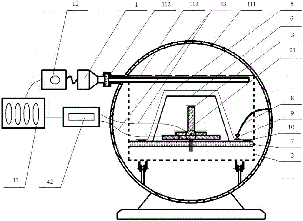
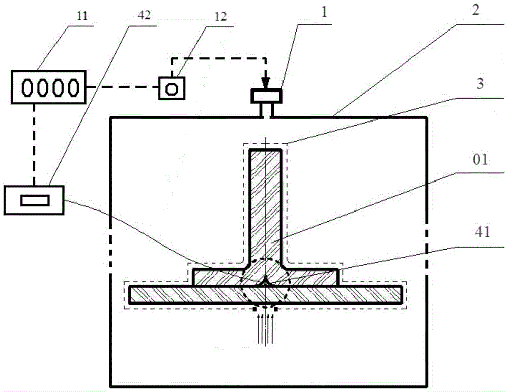
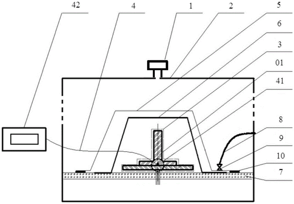
[0040] figure 1 A composite energy field heating device is provided, including a microwave heating device and an autoclave 111, the microwave heating device includes a microwave generator 1, a microwave cavity 2, a microwave partial shield 3 and a temperature measuring device 4, and the composite energy field The field heating device also includes a control system 11 and a microwave power control module 12; the microwave generator sends microwaves into the microwave cavity, and the microwave cavity is used to place the absorbing material 01, and the microwave partial shield is located in the microwave cavity and used Covering the outer surface of the microwave-absorbing material, the microwave partial shield 3 is composed of a microwave-shielding area 31 and a microwave-transmitting area 32, and the microwave-transmitting area 32 includes one or more gaps so that the microwave energy in the microwave cavity Enter the wave-absorbing material from the gap and be absorbed by it; ...


PUM

PropertyMeasurementUnit
Lengthaaaaaaaaaa

Abstract

The invention provides a composite energy field heating method. The composite energy field heating method comprises the steps that a microwave heating device is used for carrying out fixed-point heating or directional heating on a wave absorbing material, and an autoclave is used for overall heating the wave absorbing material. The method is completed through a composite energy field heating device. The composite energy field heating device comprises the microwave heating device and the autoclave. The microwave heating device comprises a microwave generator, a microwave cavity and a microwave local shielding part. The microwave generator sends microwaves into the microwave cavity. The interior of the microwave cavity is used for containing the wave absorbing material. The microwave local shielding part is located in the microwave cavity and used for covering the outer surface of the wave absorbing material, and is composed of a microwave shielding area and a microwave transmitting area. The microwave transmitting area comprises one or more clearances so that the microwaves in the microwave cavity can enter the wave absorbing material through the clearances to be absorbed by the wave absorbing material. The composite energy field heating method can really achieve temperature consistency of all the portions in the wave absorbing material, and a high-quality cured product can be provided for the field of aerospace.

Description

technical field [0001] The invention relates to the field of heating, in particular to a composite energy field heating device and method. Background technique [0002] The curing process of composite materials, such as those containing carbon fiber fabrics and resins, is a complex process of rapid changes in thermal, chemical and mechanical properties. Especially for large-sized parts, due to the complexity of its structure, such as variable thickness, multi-interface, variable structure (C-type, I-type, J-type, T-type), and the inhomogeneity of the manufacturing process environment, the part is curing It is difficult to maintain consistent temperature and pressure distribution at different parts during the process, which leads to uneven resin flow and asynchronous curing effect, which is prone to defects such as delamination, pores and fiber macroscopic slippage, and reduces the performance of the part; at the same time, due to The anisotropy of the mechanical properties ...

Claims


Application Information

Patent Timeline
IPC IPC(8): B29C70/54B29C35/08B29C35/02
CPCB29C35/0227B29C35/0288B29C35/0805B29C70/54B29C2035/0855
Inventor 湛利华陈效平韦东才黄明辉常腾飞李树健李自强丁星星
Owner CENT SOUTH UNIV
Learn More