Unmanned aerial vehicle take-off or landing control system and control method

A control system and unmanned aerial vehicle technology, used in aircraft control, landing gear, unmanned aerial vehicles, etc., can solve problems such as easy damage, and achieve the effects of extending service life, reducing energy consumption, and improving safety performance.

Active Publication Date: 2016-06-15
GEER TECH CO LTD
View PDF10 Cites 41 Cited by
  • Summary
  • Abstract
  • Description
  • Claims
  • Application Information

AI Technical Summary

Problems solved by technology

[0004] The invention provides a UAV take-off and landing control system, aiming

Method used


Image

  • Unmanned aerial vehicle take-off or landing control system and control method
  • Unmanned aerial vehicle take-off or landing control system and control method
  • Unmanned aerial vehicle take-off or landing control system and control method

Examples


Embodiment Construction

[0029] In order to make the purpose, technical solutions and advantages of the embodiments of the present invention clearer, the technical solutions in the embodiments of the present invention will be clearly and completely described below in conjunction with the drawings in the embodiments of the present invention. Obviously, the described embodiments It is a part of embodiments of the present invention, but not all embodiments. Based on the embodiments of the present invention, all other embodiments obtained by persons of ordinary skill in the art without creative efforts fall within the protection scope of the present invention.

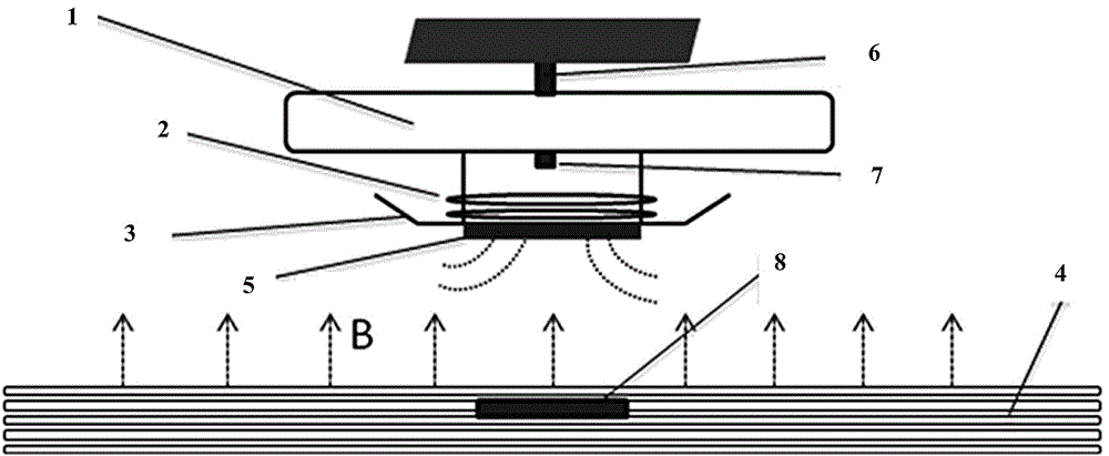
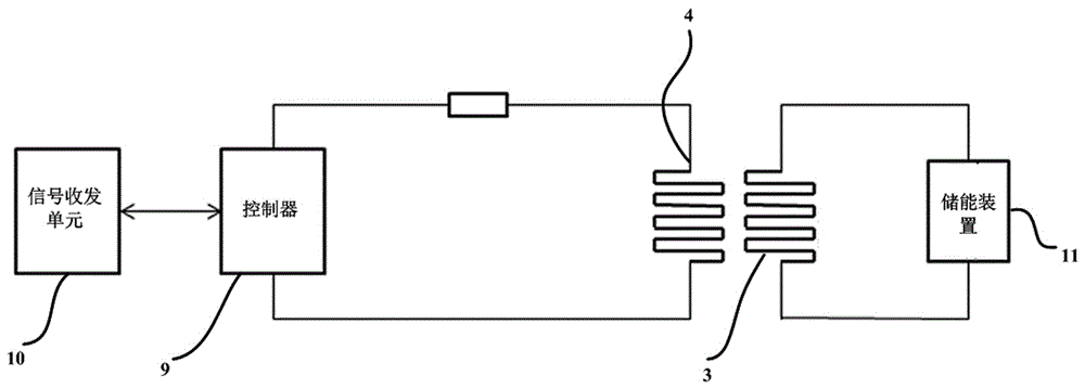
[0030] see Figure 1 to Figure 2 As shown, the landing control system disclosed in the present invention includes a magnet assembly arranged on the side of the UAV 1 and a magnetic field assembly arranged on the side of the apron. Specifically, the magnet assembly is a permanent magnet 5 arranged on the contact surface between the landing gear of...


PUM


Abstract

The invention provides an unmanned aerial vehicle take-off or landing control system which comprises a magnet assembly arranged on the side of an unmanned aerial vehicle and a magnetic field assembly arranged on the side of a parking apron. An electrification coil is arranged in the magnetic field assembly. Current is introduced into the electrification coil. A supporting magnetic field is generated by the magnetic field assembly on the side of the parking apron, so that thrust acting on the unmanned aerial vehicle is formed. Resultant force is formed by the thrust and lift force or resistance in the unmanned aerial vehicle take-off or landing process to supplement the lift force or the resistance. The invention further provides an unmanned aerial vehicle take-off or landing control method. In the unmanned aerial vehicle take-off and landing processes, the current of the electrification coil is changed to form the even magnetic field, the thrust acting on the unmanned aerial vehicle is generated to supplement the lift force or the resistance in the take-off and landing processes, the safety performance of the unmanned aerial vehicle is improved, the use energy consumption of the unmanned aerial vehicle is reduced, and the service life of the unmanned aerial vehicle is prolonged.

Description

technical field [0001] The invention relates to the technical field of unmanned aerial vehicles, in particular to a control system and control method for unmanned aerial vehicles. Background technique [0002] UAVs have a wide range of application fields such as reconnaissance / surveillance, communication relay, electronic countermeasures, disaster prevention, and emergency search. Someone in the prior art has also proposed a conceptual design, applying drones to automobiles, making them the movable "eyes" of automobiles. When the drone is not working, it is parked in the helipad on the roof and can be charged wirelessly at the same time. When working, people control the drone to detect the traffic conditions in the road ahead, and at the same time, it can act as a camera for reversing radar. [0003] However, due to the large reasons of working environment, air flow or difficult operation, the above-mentioned design concept cannot be realized yet. One of the most importan...

Claims


Application Information

Patent Timeline
IPC IPC(8): B64C19/00B64F1/00
CPCB64C19/00B64F1/00B64F1/02B64U30/20B64U70/99B64U10/25B64F1/04B64C25/32B64D45/08B64C39/024B64U50/34B64U70/00B64U70/80B64U80/86B64F1/362H01F7/202H02N15/00
Inventor 胡腾飞
Owner GEER TECH CO LTD
Why Eureka
Try Eureka