
One-way transparent low-emissivity glass

A technology of low-emissivity glass and one-way perspective, which is applied in coatings and other directions, can solve the problems of not having one-way perspective, being unable to have both one-way perspective and low-emission, and glass not having low-emission, so as to achieve one-way perspective performance , reduce observation interference, low performance effects

Inactive Publication Date: 2016-06-15
吴江南玻华东工程玻璃有限公司 +1
View PDF6 Cites 2 Cited by
  • Summary
  • Abstract
  • Description
  • Claims
  • Application Information

AI Technical Summary

Problems solved by technology

[0002] In the prior art, the glass with one-way perspective often does not have the function of low-emissivity, and the glass with low-emissivity performance does not have the function of one-way perspective, that is to say, it cannot have the dual functions of one-way perspective and low-emissivity

Method used


Image

  • One-way transparent low-emissivity glass
  • One-way transparent low-emissivity glass

Examples


Embodiment 1

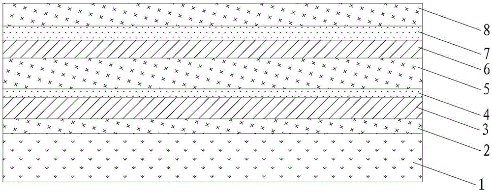
[0028] see figure 1 As shown, the structure of the one-way see-through glass is ordinary white glass substrate / ZnSnO layer / Ag layer / NiCr layer / ZnSnO layer / Ag layer / NiCr layer / Si3N4 layer, and the thickness of each layer is 6mm / 33.5nm / 25.0nm / 7.7nm / 76.2nm / 11.1nm / 1.3nm / 21.4nm. Various layers of films can be sequentially plated on the glass substrate 1 through a magnetron sputtering process, wherein 14 alternating current rotating cathodes and 5 direct current planar cathodes are used for production, a total of 19 cathodes are used for production.

[0029] The performance test of the product is as follows:

[0030] Light reflectance of glass surface (observation object surface): 56%, transmitted color: a*=-3.9, b*=-0.09;

[0031] Light reflectivity of film surface (observation surface): 18%, reflection color: a*=-15, b*=-33;

[0032] Light transmittance of viewing surface: 24%;

[0033] Emissivity: 0.02.

Embodiment 2

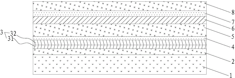
[0035] see figure 2 As shown, the structure of the one-way see-through glass is ordinary white glass substrate / ZnSnO layer / Ag layer / Cu layer / NiCr layer / ZnSnO layer / Ag layer / NiCr layer / Si3N4 layer, wherein the thickness of each layer is 6mm / 17.2 nm / 19.0nm / 6.3nm / 4.4nm / 82.6nm / 15.6nm / 0.7nm / 33.4nm, the Ag layer 31 and Cu layer 32 are stacked to form the first metal reflective layer 3 in the one-way see-through glass. Various layers of films can be sequentially plated on the glass substrate 1 through a magnetron sputtering process, wherein 12 alternating current rotating cathodes and 6 direct current planar cathodes are used for production, a total of 18 cathodes are used for production.

[0036] The performance test of the product is as follows:

[0037] Light reflectance of glass surface (observation object surface): 50%, transmitted color: a*=-0.28, b*=-3.26;

[0038] Light reflectivity of film surface (observation surface): 14%, reflection color: a*=3.5, b*=-13;

[0039] Lig...


PUM

PropertyMeasurementUnit
thicknessaaaaaaaaaa
thicknessaaaaaaaaaa
thicknessaaaaaaaaaa

Abstract

The invention discloses a one-way perspective low-emissivity glass, which comprises a glass substrate, a composite dielectric layer sequentially arranged along the thickness direction of the glass substrate, a first metal reflection layer, a preventing metal oxide layer, an intermediate composite dielectric layer, and a second metal reflection layer. Layer, light absorbing layer and composite dielectric protection layer, wherein, the thickness of the composite dielectric layer is 4-50nm, the thickness of the first metal reflection layer is 10-30nm, the thickness of the preventing metal oxide layer is 0.5-10nm, the middle composite dielectric layer The thickness of the second metal reflective layer is 5-20nm, the thickness of the light absorption layer is 0.5-20nm, and the thickness of the composite dielectric protection layer is 10-60nm. The one-way perspective low-emissivity glass has a firm, compact and simple structure, can increase the reflectivity of light on the surface of the observation object, reduce the reflectivity of light on the observation surface, reduce observation interference, and has both one-way perspective and low-radiation performance.

Description

technical field [0001] The invention relates to a one-way perspective low-radiation glass. Background technique [0002] In the prior art, one-way see-through glass often does not have the function of low-emissivity, and glass with low-emissivity performance does not have the function of one-way see-through, that is to say, it cannot have the dual functions of one-way see-through and low-emissivity. Contents of the invention [0003] The object of the present invention is to provide a glass with one-way perspective function and low radiation performance. [0004] In order to achieve the above object, the technical solution adopted by the present invention is: a kind of one-way perspective low-emissivity glass, the glass includes a glass substrate, a composite dielectric layer arranged in sequence along the thickness direction of the glass substrate, a first metal reflective layer, prevent the metal oxide layer, the intermediate composite dielectric layer, the second m...

Claims


Application Information

Patent Timeline
Patent Type & Authority Applications(China)
IPC IPC(8): C03C17/36
CPCC03C17/36C03C17/3618C03C17/3626C03C17/3639C03C17/3652C03C17/366C03C2217/73C03C2218/156
Inventor 许莉丽宋保柱米永江
Owner 吴江南玻华东工程玻璃有限公司
Learn More