Textile drying device

A drying device and textile technology, applied in the directions of drying, drying machine, drying gas arrangement, etc., can solve the problems of affecting the production efficiency of textiles, rapid heat loss of drying box, single heat source of drying machine, etc. The drying time is saved, the structure is simple, and the drying efficiency is improved.

Inactive Publication Date: 2016-06-15
RUIAN AOYA CLOTHING CO LTD
View PDF0 Cites 12 Cited by
  • Summary
  • Abstract
  • Description
  • Claims
  • Application Information

AI Technical Summary

Problems solved by technology

[0002] Dryer is one of the indispensable production equipment in textile production. The quality of the dryer will directly affect the quality of the textile. The drying box of the existing dryer is usually a metal shell. As a result, the heat in the drying box is also lost quickly, and the existing dryer has a single heat source, the drying speed is slow, the drying time is long, and the efficiency is low, which directly affects the production efficiency of textiles.

Method used


Image

  • Textile drying device

Examples


Embodiment Construction

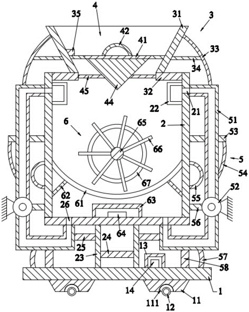
[0020] Such as figure 1 As shown, the textile drying device of the present invention includes a bottom plate 1, a frame located above the bottom plate 1, a feeding device 3 located above the frame 2, and a cover device 4 located in the feeding device 3 , Air circulation devices 5 located on the left and right sides of the frame 2 and heating devices 6 located in the frame 2.

[0021] Such as figure 1 As shown, the bottom plate 1 is a rectangular parallelepiped, the bottom plate 1 is placed horizontally, and the bottom plate 1 is provided with a first support block 11 below it, a first roller 12 located below the first support block 11, and A fixed frame 13 above the bottom plate 1 and a power source 14 located in the fixed frame 13. The first support blocks 11 are provided with two and are respectively located on the left and right sides below the bottom plate 1. The first support blocks 11 are columns with an isosceles trapezoid in cross section, and the first support blocks 1...


PUM


Abstract

A textile drying device, comprising a bottom plate, a frame body, a feeding device, a cover plate device, an air circulation device, and a heating device. The bottom plate is provided with a first support block, a first roller, a fixed frame, and a power supply. There are a first through hole, a filter frame, a first support rod, a first cross bar, a second cross bar and a second through hole, and the feeding device includes a feed hopper, a horizontal plate, a first bending rod, a third cross bar and The first fixed block, the cover plate device includes a cover plate, a grip ring, a diverter block and a first horizontal plate, and the air circulation device includes a pipe, a fan, a fourth horizontal bar, a second bending bar, an elastic bar, a first connecting bar, The third bending rod and the second supporting rod, the heating device includes an iron net, an inclined rod, a heat dissipation frame, a heating rod, a rotating shaft, a rotating rod and a supporting ring. The present invention can thoroughly dry the textiles with high drying efficiency. And the drying effect is good.

Description

Technical field [0001] The invention relates to the technical field of textile equipment, in particular to a textile drying device. Background technique [0002] The dryer is one of the indispensable production equipment in the production of textiles. The quality of the dryer will directly affect the quality of the textiles. The drying box of the existing dryers is usually a metal shell. Fast, resulting in faster heat loss in the drying box, and the existing dryer has a single heat source, slow drying speed, long drying time and low efficiency, which directly affects the production efficiency of textiles. [0003] Therefore, it is necessary to provide a new technical solution to solve the above technical problems. Summary of the invention [0004] The purpose of the present invention is to provide a textile drying device which can effectively solve the above technical problems. [0005] In order to solve the above technical problems, the present invention adopts the following techni...

Claims


Application Information

Patent Timeline
Patent Type & Authority Applications(China)
IPC IPC(8): F26B11/16F26B21/00F26B25/04
CPCF26B11/16F26B21/00F26B25/04
Inventor 陈杨
Owner RUIAN AOYA CLOTHING CO LTD
Why Eureka
Try Eureka