Maze type micro-fluid delay flow control unit

A labyrinth and fluid technology, which is applied in the research and development of medical instant detection products, can solve the problems of inability to realize multiple detections in linkage, and achieve the effect of improving detection sensitivity and accuracy.

Inactive Publication Date: 2016-06-15
DALIAN UNIV OF TECH
View PDF8 Cites 4 Cited by
  • Summary
  • Abstract
  • Description
  • Claims
  • Application Information

AI Technical Summary

Problems solved by technology

However, the flow control units mentioned above can only allow a relatively limited liquid to flow through the channel cross-section, and cannot realize multiple detections in conjunct

Method used


Image

  • Maze type micro-fluid delay flow control unit
  • Maze type micro-fluid delay flow control unit
  • Maze type micro-fluid delay flow control unit

Examples


Embodiment Construction

[0029] The specific embodiments described here are only used to explain the present invention, not to limit the present invention.

[0030] Below, the specific embodiment of the present invention is described in conjunction with accompanying drawing:

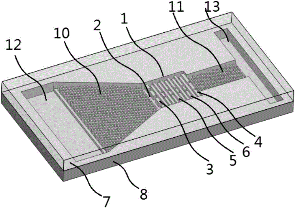
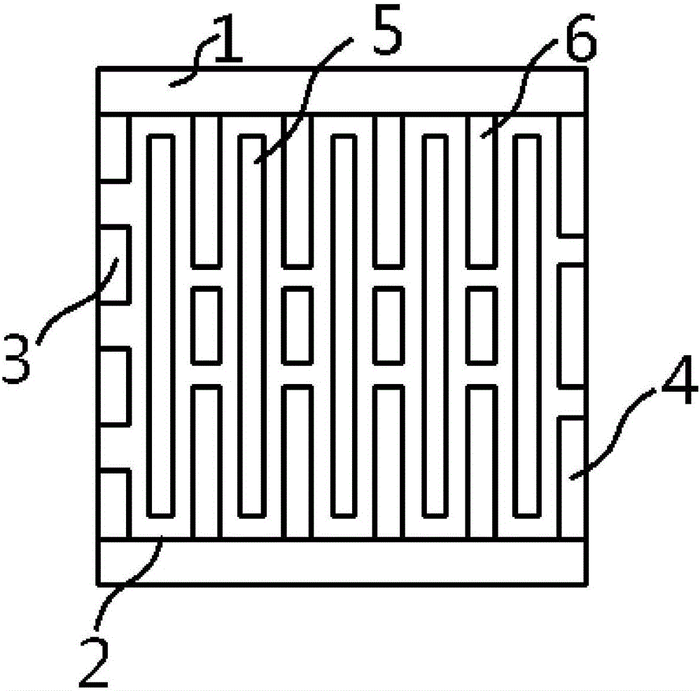
[0031] The labyrinth entrance boss structure is composed of four rectangular bosses located at the front end of the channel. The centers of these four rectangular bosses are on the same cross section of the channel, and two of the rectangular bosses are in contact with the channel wall.

[0032] The labyrinth exit boss structure is composed of three rectangular bosses located at the rear end of the channel. The centers of these three rectangular bosses are on the same cross section of the channel, and two of the rectangular bosses are in contact with the channel wall.

[0033]The No. 1 labyrinth wall boss structure consists of a long rectangular boss.

[0034] The boss structure of No. 2 labyrinth wall is composed of 3 rectangu...


PUM

PropertyMeasurementUnit
Widthaaaaaaaaaa
Widthaaaaaaaaaa
Lengthaaaaaaaaaa

Abstract

The invention provides a maze type micro-fluid delay flow control unit and belongs to the field of medical instant detection product researches.The maze type blood sample delay flow control unit is used for controlling the flowing of a thrombus instant detection POCT product in fluid.Liquid flowing states can be controlled by regulating the feature sizes of a maze entrance boss structure (3), a maze exit boss structure (4), a first maze wall boss structure (5), a second maze wall boss structure (6) and channels, and accordingly flowing time of the fluid flowing through the channels is controlled.By controlling the fluid flowing time, the antigen in a to-be-detected blood sample is allowed to be fully mixed with the antibody on the POCT chip product, detection reaction time is controlled, the detection sensitivity and accuracy of the POCT detection product are increased, and good detection results can be obtained.

Description

technical field [0001] The invention relates to a labyrinth microfluid time-delayed flow control unit, which belongs to the field of research and development of instant medical detection products. Background technique [0002] In the early 1990s, the concept of Micro Total Analysis System (μ-TAS), also known as Lab-on-a-chip (Lab-on-a-chip), was proposed by Manz in Switzerland. had a profound impact. As the development direction of the micro-total analysis system, the microfluidic chip is a microfabrication technology based on a substrate with a size of a few square centimeters to create a microchannel network structure and integrate other functional units to achieve sample preparation, processing A fast, efficient and low-cost micro-analysis system integrating sample, reaction, separation and detection. Microfluidic chips have broad application prospects in many aspects such as genome sequencing, protein analysis, drug screening, and immunological assays. [0003] The ap...

Claims


Application Information

Patent Timeline
IPC IPC(8): G01N33/558
CPCG01N33/558
Inventor 李经民张斌刘冲梁超刘军山王立鼎
Owner DALIAN UNIV OF TECH
Why Eureka
Try Eureka