Device and method for detecting response non-uniformity and linearity of CCD

A technology of non-uniformity and detection device, applied in the direction of measurement device, measurement of electricity, measurement of electric variables, etc., can solve the problem of response non-uniformity and low detection accuracy of linearity, difficult to avoid the stability of integrating sphere, unable to eliminate detection errors, etc. problem, to achieve the effect of controllable detection, reduction of measurement error, and reduction of detection error

Inactive Publication Date: 2016-06-15
LASER FUSION RES CENT CHINA ACAD OF ENG PHYSICS
View PDF5 Cites 3 Cited by
  • Summary
  • Abstract
  • Description
  • Claims
  • Application Information

AI Technical Summary

Problems solved by technology

The detection method using the integrating sphere is more complicated and expensive, and it is difficult to avoid the stability of the output of the integrating sphere under different parameters
In addition, it is difficult to trace the source of the integrating sphere, and no organization can identify the error

Method used


Image

  • Device and method for detecting response non-uniformity and linearity of CCD
  • Device and method for detecting response non-uniformity and linearity of CCD
  • Device and method for detecting response non-uniformity and linearity of CCD

Examples


Embodiment 1

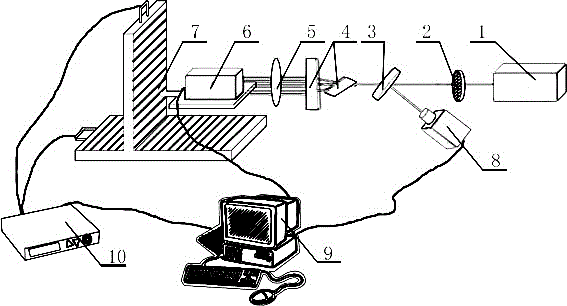
[0057] A CCD response non-uniformity and linearity detection device, including a test light source 1, an attenuation film 2, a sampling mirror 3, an optical pair 3, a telephoto converging lens 5, a CCD to be tested 6, a two-dimensional translation stage 7, and an energy meter 8 , a computer 9, a controller 10 and a black box, the incident laser light produced by the test light source 1 passes through the attenuation sheet 2 and the sampling mirror 3 in turn to generate reflected laser light and transmitted laser light on the sampling mirror 3, and the reflected laser light is directly incident on the energy meter 8. The transmitted laser light is incident on the CCD 6 to be tested after passing through the optical pair 3 and the telephoto converging lens 5 in sequence. All placed in a black box, the two-dimensional translation stage 7 is electrically connected to the controller 10, and the CCD 6 to be tested, the energy meter 8 and the controller 10 are all electrically connect...

Embodiment 2

[0059] A CCD response non-uniformity and linearity detection device, including a test light source 1, an attenuation film 2, a sampling mirror 3, an optical pair 3, a telephoto converging lens 5, a CCD to be tested 6, a two-dimensional translation stage 7, and an energy meter 8 , a computer 9, a controller 10 and a black box, the incident laser light produced by the test light source 1 passes through the attenuation sheet 2 and the sampling mirror 3 in turn to generate reflected laser light and transmitted laser light on the sampling mirror 3, and the reflected laser light is directly incident on the energy meter 8. The transmitted laser light is incident on the CCD 6 to be tested after passing through the optical pair 3 and the telephoto converging lens 5 in sequence. All placed in a black box, the two-dimensional translation stage 7 is electrically connected to the controller 10, and the CCD 6 to be tested, the energy meter 8 and the controller 10 are all electrically connect...

Embodiment 3

[0062] A CCD response non-uniformity and linearity detection device, including a test light source 1, an attenuation film 2, a sampling mirror 3, an optical pair 3, a telephoto converging lens 5, a CCD to be tested 6, a two-dimensional translation stage 7, and an energy meter 8 , a computer 9, a controller 10 and a black box, the incident laser light produced by the test light source 1 passes through the attenuation sheet 2 and the sampling mirror 3 in turn to generate reflected laser light and transmitted laser light on the sampling mirror 3, and the reflected laser light is directly incident on the energy meter 8. The transmitted laser light is incident on the CCD 6 to be tested after passing through the optical pair 3 and the telephoto converging lens 5 in sequence. All placed in a black box, the two-dimensional translation stage 7 is electrically connected to the controller 10, and the CCD 6 to be tested, the energy meter 8 and the controller 10 are all electrically connect...


PUM


Abstract

The invention discloses a device and method for detecting response non-uniformity and linearity of a CCD, and belongs to devices and methods for detecting response non-uniformity and linearity in the technical field of optical imaging and digital image processing and analysis. The detecting device includes a test light source, an attenuation sheet, a sampling mirror, an optical wedge pair, a long-focal-length convergent lens, a CCD to be detected, a two-dimensional translation table, an energy meter, a computer, a controller and a dark box, incident laser generated by the test light source passes through the attenuation sheet and the sampling mirror in sequence and then reflection laser and transmission laser are generated, the reflection laser is directly incident to the energy meter, the transmission laser passes through the optical wedge pair and the long-focal-length convergent lens in sequence and is incident to the CCD to be detected, the CCD to be detected is installed on the two-dimensional translation table, the two-dimensional translation table is electrically connected with the controller, and the CCD to be detected, the energy meter and the controller are electrically connected with the computer. The device and method provided by the invention are suitable for detection of response non-uniformity and linearity of the CCD.

Description

technical field [0001] The invention belongs to the technical field of optical imaging and digital image processing and analysis, and relates to a detection device and a detection method for CCD response non-uniformity and linearity. Background technique [0002] CCD (Charge Coupled Device) is a photoelectric conversion device that converts optical signals into electrical signals through the photoelectric effect, and transfers and stores electrical signals. The non-uniformity of CCD response refers to the difference of the output signal of each photosensitive element of CCD under the completely uniform light irradiation. [0003] Among the many parameters describing CCD, there are two extremely important parameters: response non-uniformity and linearity. When detecting the non-uniformity and linearity of CCD response, the conventional detection method is to use an integrating sphere or a collimator for detection: the CCD is uniformly irradiated through the integrating spher...

Claims


Application Information

Patent Timeline
IPC IPC(8): G01R31/26
CPCG01R31/2601G01R31/2641
Inventor 郑垠波丁磊周信达巴荣声袁静徐宏磊姜宏振张霖杨晓瑜陈波
Owner LASER FUSION RES CENT CHINA ACAD OF ENG PHYSICS
Why Eureka
Try Eureka