

Photo alignment device and photo alignment method
A technology of photo-alignment and polarized light, applied in the field of photo-alignment
- Summary
- Abstract
- Description
- Claims
- Application Information
AI Technical Summary
Problems solved by technology
Method used
Image

Examples
Embodiment Construction
[0140] Next, modes for carrying out the invention of the present application (hereinafter referred to as embodiments) will be described.
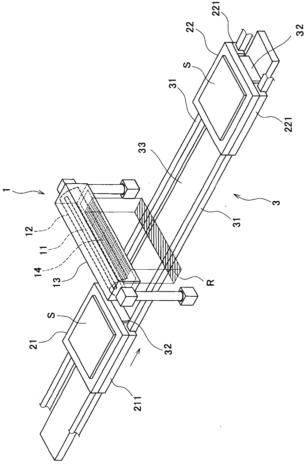
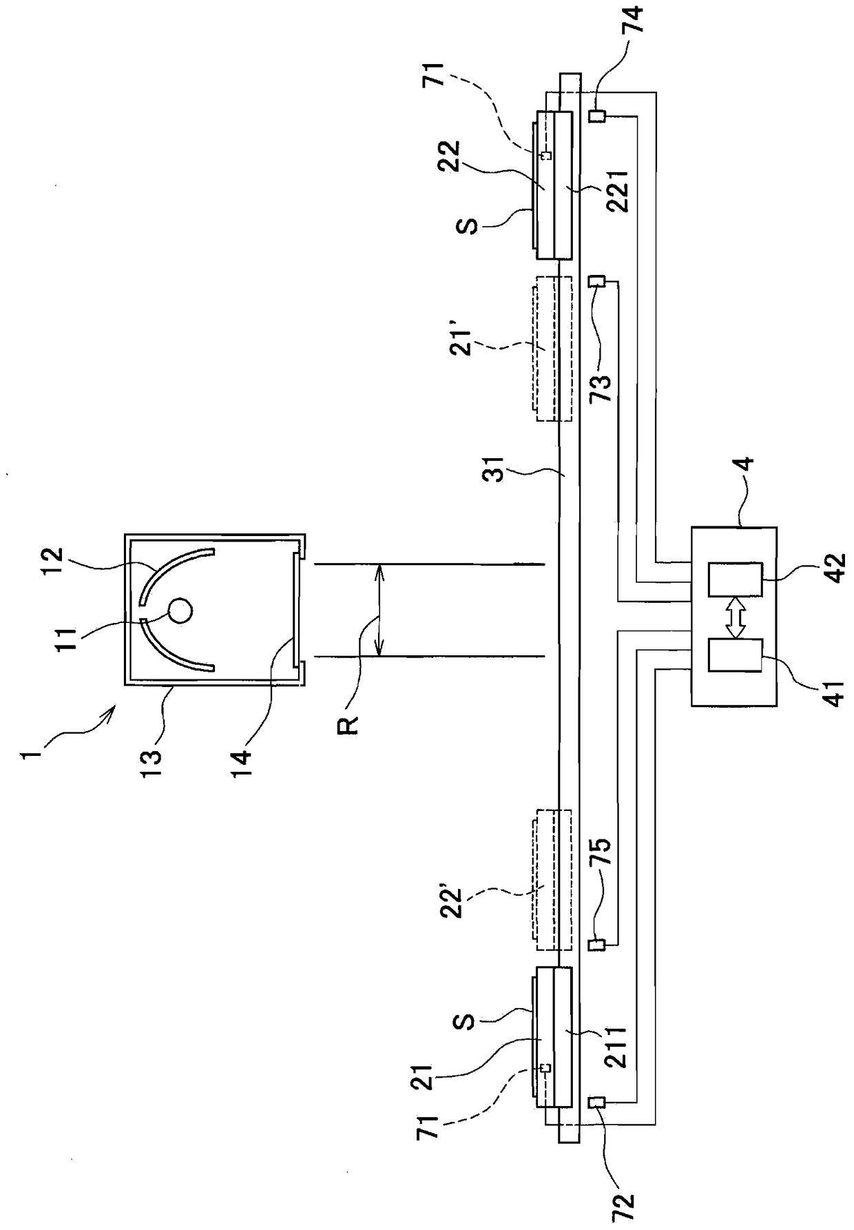
[0141] figure 1 It is a perspective schematic view of the photo-alignment device which concerns on 1st Embodiment. figure 1 The shown photo-alignment device includes: an irradiation unit 1 that irradiates polarized light toward a set irradiation region R; stages 21 and 22 on which a substrate S is placed; The stage moving mechanism 3 that irradiates polarized light to the liquid crystal substrate S on the stages 21 and 22 .
[0142]The irradiation unit 1 irradiates polarized light in a substantially rectangular pattern, and the area of the pattern is an irradiation region R. FIG. The irradiation area R is set as an area within the horizontal plane.
[0143] The stage moving mechanism 3 is a mechanism for moving the stages 21 and 22 so as to pass through the irradiation area R described above. In this embodiment, the tables 21 and 22 a...
PUM
 Abstract
Description
Claims
Application Information