
Self-circulation liquid cooling permanent magnetic motor of high power rate

A permanent magnet motor, self-circulation technology, applied in electrical components, electromechanical devices, electric components, etc., can solve the problems of heat dissipation and cooling of the sealed motor rotor, poor power density, large motor volume, etc., achieve good heat dissipation effect, improve Heat dissipation effect, the effect of increasing the heat absorption area

Active Publication Date: 2016-06-15
扬州科光技术发展有限公司
View PDF10 Cites 4 Cited by
  • Summary
  • Abstract
  • Description
  • Claims
  • Application Information

AI Technical Summary

Problems solved by technology

[0003] Although there are many technical patents for permanent magnet brushless motors in China, there are still technical bottlenecks in the motor. At present, there are a large number of technical patents for water-cooled motors, which only achieve water-cooled heat dissipation for the motor stator, and cannot solve the problem of heat dissipation and cooling for the rotor of sealed motors.
The rotor will generate high temperature during the working process. The permanent magnets of the current high-power motor rotors are made of high-temperature-resistant samarium-cobalt materials. Motors made of samarium cobalt are larger in size and poor in power density

Method used


Image

  • Self-circulation liquid cooling permanent magnetic motor of high power rate
  • Self-circulation liquid cooling permanent magnetic motor of high power rate
  • Self-circulation liquid cooling permanent magnetic motor of high power rate

Examples


Embodiment Construction

[0027] Below in conjunction with accompanying drawing and specific embodiment, further illustrate the present invention, it should be understood that these embodiments are only used to illustrate the present invention and are not intended to limit the scope of the present invention, after reading the present invention, those skilled in the art will understand various aspects of the present invention Modifications in equivalent forms all fall within the scope defined by the appended claims of this application.

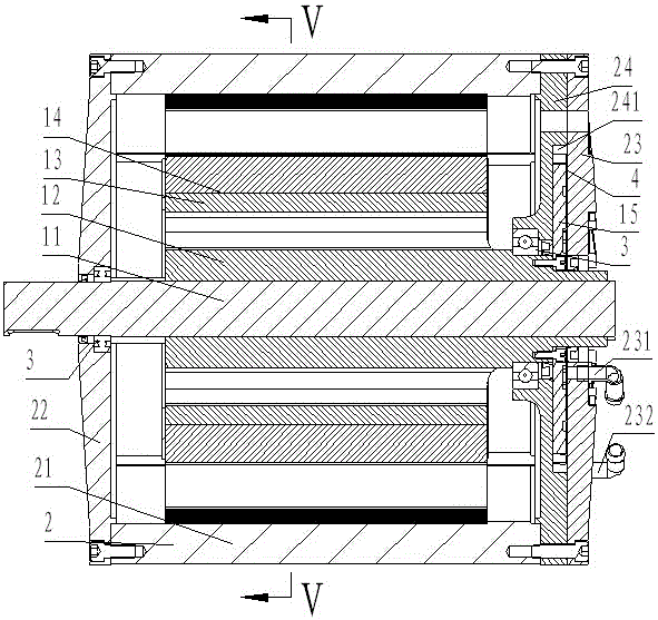
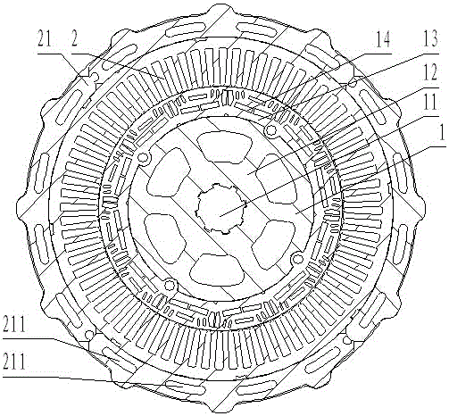
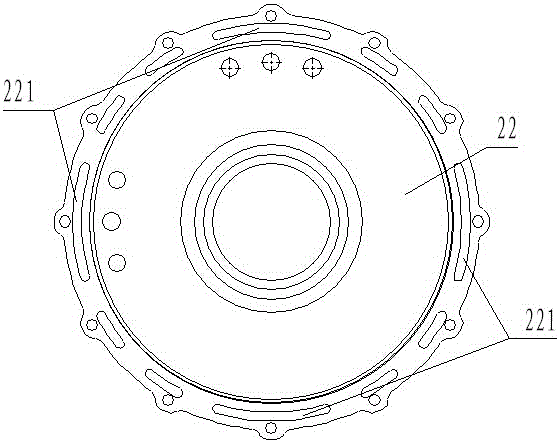
[0028] Such as figure 1 , Figure 8 with Figure 9 As shown, a high power ratio self-circulating liquid-cooled permanent magnet motor includes a rotor 1 and a stator 2. The rotor 1 includes a main shaft 11, a metal bracket 12 sleeved outside the main shaft, a magnetic pole sleeve 13 sleeved outside the metal bracket and The magnetic pole bundle 14 embedded in the magnetic pole sleeve 13 is connected with the pump impeller 15 at the rear end of the rotor through bolts....


PUM


Abstract

The invention discloses a self-circulation liquid cooling permanent magnetic motor of high power rate. The motor comprises a stator and a rotor, the stator sleeves the rotor, the rotor comprises a metal rotor and a metal main shaft, the metal rotor sleeves the metal main shaft, the stator is arranged in a liquid pump chamber, a liquid inlet is arranged in the middle portion of the liquid pump chamber, a liquid outlet is arranged in an edge position of the liquid pump chamber, and a pump impeller made of a heat radiation material and connected with the main shaft of the rotor are arranged in the liquid pump chamber. The pump impeller made of the heat radiation material is immersed in the low-temperature environment of the liquid pump chamber, when the motor rotates and works, under the effect of the pump impeller, a liquid coolant circulates continuously to take away heat of the rotor, a permanent magnet is prevented from failure caused by demagnetization, it is ensured that the permanent magnetic motor is long in service life and high in efficiency, the risk of demagnetization of the motor is greatly reduced, the power rate and performance of the motor is greatly improved, and the size, weight and cost of the motor are reduced.

Description

technical field [0001] The invention relates to a motor, in particular to a high power ratio self-circulating liquid-cooled permanent magnet motor with heat dissipation function. Background technique [0002] With the continuous progress and development of society, in order to put forward high-efficiency, energy-saving and emission-reduction requirements for various vehicles, there are certain requirements for the performance of the motor. It is required that the high-efficiency motor must reach a certain power density ratio. To reduce the volume of the motor and reduce the consumption of raw materials, especially when the motor is required to be sealed and waterproof, for safe and reliable operation, it is important to optimize the design of the motor. [0003] Although there are many technical patents for permanent magnet brushless motors in China, there are still technical bottlenecks in the motor. At present, there are a large number of technical patents for water-cooled...

Claims


Application Information

Patent Timeline
Patent Type & Authority Applications(China)
IPC IPC(8): H02K9/19H02K5/20
CPCH02K5/20H02K9/19
Inventor 戴杰戴嘉祯
Owner 扬州科光技术发展有限公司
Learn More