
An integrated high temperature resistant electromagnetic induction coil

An electromagnetic induction coil, high temperature resistant technology, applied in the direction of induction heating, coil devices, etc., can solve the problems of coil inductance stability and life-span adverse effects, inductance linearity space position drift, etc., to improve impact resistance and tensile strength , good sealing effect

Active Publication Date: 2019-06-28
DALIAN UNIV OF TECH
View PDF3 Cites 0 Cited by
  • Summary
  • Abstract
  • Description
  • Claims
  • Application Information

AI Technical Summary

Problems solved by technology

Since the wire is not completely fixed, the linearity of the inductance of this coil may drift due to the change of its spatial position due to the deformation of the wire for a long time in a high temperature environment, and because the wire is not completely sealed, oxidation and dust at high temperature are both May adversely affect the stability and life of the coil inductance

Method used


Image

  • An integrated high temperature resistant electromagnetic induction coil
  • An integrated high temperature resistant electromagnetic induction coil

Examples


Embodiment 1

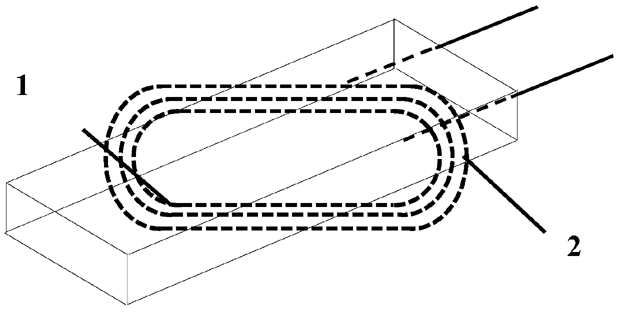
[0012] Embodiment 1, the nickel wire of outsourcing inorganic high-temperature-resistant insulating skin is coiled into the shape of electromagnetic induction coil 1 and pressed into the electrical insulation amorphous refractory castable or ceramic powder stirred with solvent, and the terminal of the coil is kept outside. Pound to drive out the air bubbles in the amorphous refractory castable or ceramic powder, so that the electromagnetic induction coil 1 is closely combined with the amorphous refractory castable or ceramic powder. After the amorphous refractory castable is completely solidified or the ceramic powder is sintered, the internal An electrically insulating refractory material entity 2 including an electromagnetic induction coil 1, this structure can be used for inductive deviation correction in a high temperature environment (500-1200°C).

Embodiment 2

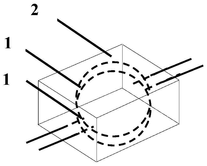
[0013] Embodiment 2, the nickel wire of the outsourcing inorganic high-temperature-resistant insulating skin is coiled into two electromagnetic induction coils 1 arranged up and down, and pressed into the electrically insulating amorphous refractory castable or ceramic powder stirred with the solvent, and the terminals of the coils are kept Externally, by vibrating, the air bubbles in the unshaped refractory castable or ceramic powder are driven out, so that the electromagnetic induction coil 1 is closely combined with the unshaped refractory castable or ceramic powder, and after the unshaped refractory castable is completely solidified or the ceramic powder is sintered , the electrical insulating refractory material entity 2 that contains two electromagnetic induction coils 1 can be obtained. One of the two internal electromagnetic induction coils 1 can be used as a transmitting coil, and the other can be used as a receiving coil. This internally contains two electromagnetic in...


PUM


Abstract

The invention belongs to the technical filed field of non-contact measurement and control under a high-temperature environment and relates to an integrated high temperature resistant electromagnetic induction coil. A nickel wire which is used for transmitting or receiving signals and is coated with an inorganic high temperature resistant insulating sheath is coiled to one or a plurality of coils which are completely embedded in electrically-insulated unshaped refractory castable or electrically-insulated ceramic powder; based on the curing of the electrically-insulated unshaped refractory castable or the sintering of the electrically-insulated ceramic powder, the coils which are formed by coiling the nickel wire which is coated with the inorganic high temperature resistant insulating sheath can be completely and tightly combined with the cured electrically-insulated unshaped refractory castable or the sintered electrically-insulated ceramic powder, so that the integrated high temperature resistant electromagnetic induction coil can be formed. The integrated high temperature resistant electromagnetic induction coil can work steadily for a long time under a high-temperature environment of 500 DEG C to 1200 DEG C and can be used for high-temperature correction, high-temperatures proximity switches or high-temperature metal detectors.

Description

technical field [0001] The invention belongs to the technical field of non-contact measurement and control under high temperature environment, and relates to an integrated high temperature resistant electromagnetic induction coil. Background technique [0002] At present, in the field of non-contact measurement and control technology under high temperature environment, the core component mainly involved is the electromagnetic induction coil that can work stably for a long time under high temperature environment. For example, there are three main types of deviation correction systems involved in normal temperature strip production, namely inductive, photoelectric and capacitive deviation correction. However, when it comes to deviation correction in high temperature environments, due to the high ambient temperature In the continuous annealing furnace for rolling, the temperature in the furnace may reach 900°C, and the dust is relatively large. In such a harsh environment, gene...

Claims


Application Information

Patent Timeline
Patent Type & Authority Patents(China)
IPC IPC(8): H05B6/36
CPCH05B6/36
Inventor 赖康生王晓旭许青
Owner DALIAN UNIV OF TECH
Learn More