
Electromagnetic induction wire coil and automatic cooking machine thereof

An electromagnetic induction, automatic cooking technology, applied in induction heating, application, coil device and other directions, can solve the problems of tumbling food shape, paste bottom, bottom overheating, etc., to achieve high installation and production efficiency, avoid food paste bottom, ensure heating aging effect

Active Publication Date: 2016-06-15
JOYOUNG CO LTD
View PDF5 Cites 1 Cited by
  • Summary
  • Abstract
  • Description
  • Claims
  • Application Information

AI Technical Summary

Problems solved by technology

[0002] At present, electric cooking appliances on the market, especially automatic frying pans, have conventional heating plate heating, halogen tube heating and electromagnetic heating. Because the energy of electromagnetic is controllable and energy-saving is the most widely used, the layout of the electromagnetic coil is mostly on the bottom. The main heating and side auxiliary heating are used to complete the so-called three-dimensional heating. This is also designed to match the pan with a flat bottom to facilitate the sharing of ingredients. However, with this layout, the tumbling of the ingredients is not thorough, especially for cooking such as tofu and tomato scrambled eggs. Such ingredients cannot be rolled completely without damaging the shape of the ingredients
And because the bottom is heated, this kind of food can easily cause the risk of sticking the bottom, resulting in the problem of overheating the bottom and insufficient heating of the upper part.

Method used


Image

  • Electromagnetic induction wire coil and automatic cooking machine thereof
  • Electromagnetic induction wire coil and automatic cooking machine thereof
  • Electromagnetic induction wire coil and automatic cooking machine thereof

Examples


no. 1 approach

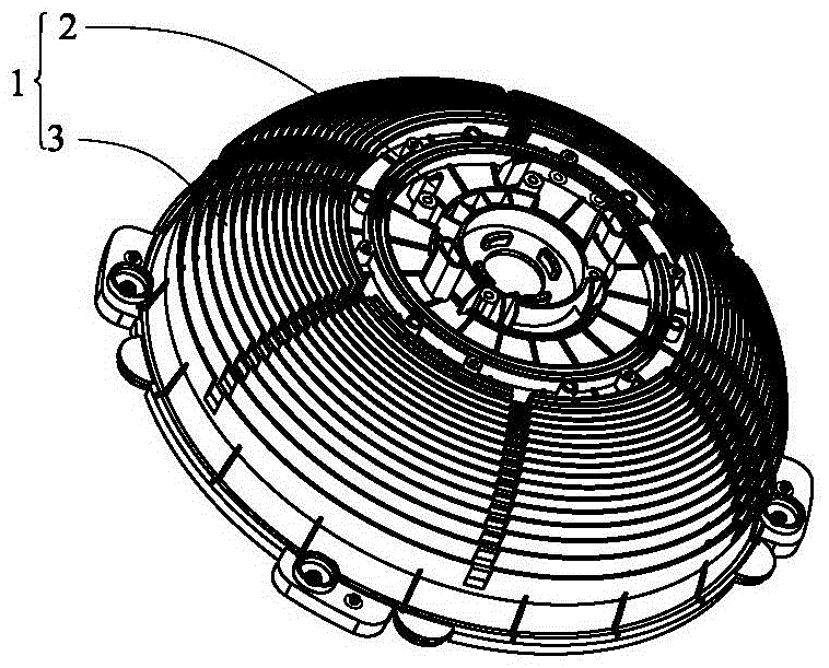
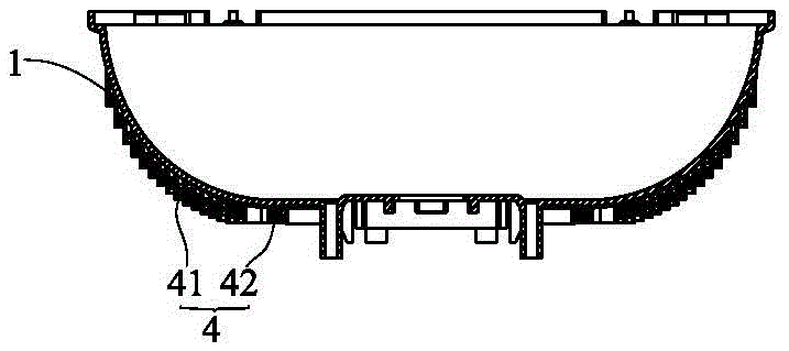
[0032] Such as figure 1 , figure 2 As shown, the first embodiment of an electromagnetic induction coil in the present invention includes: a coil body 1, the coil body includes a bottom wall 2 and an upwardly extending arc-shaped side wall 3; a coil winding 4, the coil The winding 4 includes a side induction coil 41 and a bottom induction coil 42; the coil winding 4 is wound on the wire disc body 1, the number of turns of the side induction coil 41 is greater than the number of turns of the bottom induction coil 42, and the bottom induction coil is arranged on the bottom wall peripheral.

[0033] In this embodiment, the cable tray body 1 is integrally formed and has a hemispherical shape as a whole, including a bottom wall 2 and an arc-shaped side wall 3 extending upward. The coil body is provided with a winding slot corresponding to the coil winding, and the number of turns of the side induction coil in the winding slot is greater than the number of turns of the bottom indu...

Embodiment approach 2

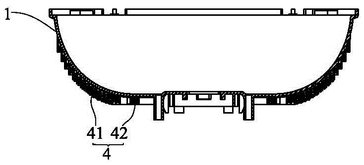
[0049] see image 3 As shown, the second embodiment of an electromagnetic induction reel in the present invention differs from the first embodiment in that the number of winding layers of the side induction coil 41 is greater than the number of winding layers of the bottom induction coil 42 .

[0050] In this way, it is further ensured that the arc-shaped side wall of the electromagnetic induction coil of the present invention generates more heat than the bottom wall, thereby ensuring the effect of three-dimensional heating.

[0051]Further, the winding layers of the side induction coil 41 are 2-4 layers, and the winding layers of the bottom induction coil 42 are 1-2 layers. Certainly, when the side induction coil 41 is wound, the number of local layers can also be more, for example, the middle part of the side induction coil 41 has more layers than the two sides, or the layers are arranged alternately. In general, it can ensure that the heat of the side induction coil 41 is...

Embodiment approach 3

[0054] see Figure 4 As shown, an embodiment of an automatic cooking machine of the present invention includes a pot 5 and an electromagnetic induction wire reel, the electromagnetic induction wire reel is located at the bottom of the pot 5, and in the cooking state, the pot 5 and the electromagnetic induction wire The pans are tilted together.

[0055] The electromagnetic induction coil described above is one of the first or second embodiment.

[0056] In this embodiment, the pot 5 includes a bottom wall 51, a side wall 52 and an arc-shaped transition portion 53, and the coil winding on the arc-shaped side wall of the electromagnetic induction coil covers at least 1 / 2 of the arc-shaped transition portion 53 area. In this way, it can effectively ensure that the side induction coil of the electromagnetic induction coil heats the arc-shaped transition portion of the pan to ensure the cooking effect. Further, the side induction coil completely covers the arc-shaped transition p...


PUM


Abstract

The invention relates to an electromagnetic induction wire coil and an automatic cooking machine thereof. The electromagnetic induction wire coil comprises a wire coil body and a coil winding, wherein the wire coil body comprises a bottom wall and an arc side wall upwards extending, the coil winding comprises a lateral induction coil and a bottom induction coil and is wound around the wire coil body, the turns of the lateral induction coil is greater than the turns of the bottom induction coil, and the bottom induction coil is arranged at the periphery of the bottom wall. Therefore, a traditional wire coil structure is improved, the side surface of the wire coil provides a main heating region, an auxiliary heating region is arranged at the bottom wall to form more reliable three-dimensional heating, the risk of food sticking to the bottom is avoided, and the food is also enabled to be fully heated and cooked; and moreover, the bottom induction coil and the lateral induction coil can be favorably linked in a three-dimensional way, and the three-dimensional heating effect is ensured.

Description

technical field [0001] The invention belongs to the field of kitchen appliances, in particular to an electromagnetic induction reel and an automatic cooking machine thereof. Background technique [0002] At present, electric cooking appliances on the market, especially automatic frying pans, have conventional heating plate heating, halogen tube heating and electromagnetic heating. Because the energy of electromagnetic is controllable and energy-saving is the most widely used, the layout of the electromagnetic coil is mostly on the bottom. The main heating and side auxiliary heating are used to complete the so-called three-dimensional heating. This is also designed to match the pan with a flat bottom to facilitate the sharing of ingredients. However, with this layout, the tumbling of the ingredients is not thorough, especially for cooking such as tofu and tomato scrambled eggs. Such ingredients cannot be rolled completely without damaging the shape of the ingredients. And be...

Claims


Application Information

Patent Timeline
IPC IPC(8): H05B6/40A47J27/00A47J36/24
Inventor 朱泽春刘远张岱
Owner JOYOUNG CO LTD
Learn More