
Linear temperature sensor

a temperature sensor and linear technology, applied in the field of linear temperature sensors, can solve the problems of the principal cost of such distributed sensors, rather than the sensor or interface, and achieve the effects of limiting the applicability of mcdes, low cost, and high level outpu

Inactive Publication Date: 2002-02-05
AIRPAX
View PDF6 Cites 51 Cited by
  • Summary
  • Abstract
  • Description
  • Claims
  • Application Information

AI Technical Summary

Problems solved by technology

In fact, a principal cost of such distributed sensors is the cabling and connectors, rather than the sensor or interface.

Method used


Image

  • Linear temperature sensor
  • Linear temperature sensor
  • Linear temperature sensor

Examples


example 2

FIG. 4 shows a control system including a plurality of temperature sensors 5, 7, according to Example 1, a microcontroller 1 having a multiplexer 5 and digital to analog converter 6 for receiving the temperature sensor inputs, and an actuator 8 for controlling a system. One of the temperature sensors 7 is connected by cable 9 to a microcontroller housing 2, while the other temperature sensor 5 resides within the microcontroller housing 2. Each temperature sensor 5, 7, has a respective bias resistor R.sub.B1, R.sub.B2 located within the microcontroller housing 2.

example 3

FIG. 4 shows a first embodiment of a sensor probe according to the present invention. The probe includes a set 10 of four 1N4148 diodes in series, at the tip of an assembly. A cap 12 fits over the set 10 of diodes. A connector 11 allows connection of a sensor cable to interface the sensor with a data acquisition system or control system. This design is suitable for sensing air temperatures.

FIGS. 6A and 6B shows a top and partial cutaway side view of an alternate embodiment of the sensor, suitable for immersion in liquid. Inside the tip of the sensor probe, a set 20 of four 1N4148 diodes are provided in close proximity. The set 20 of diodes are set within a Mylar insulator and thermal grease is used to provide good thermal contact. An sealed connector 21 allows connection with a sensor cable. The connector 12 has two conductors within a sealing member 22, and is preferably a Metri-Pack 150 series Packard Connector, which mates with Packard Connector P / N 12040753.

FIG. 7 shows a side c...


PUM

PropertyMeasurementUnit
voltage dropaaaaaaaaaa
voltageaaaaaaaaaa
voltageaaaaaaaaaa

Abstract

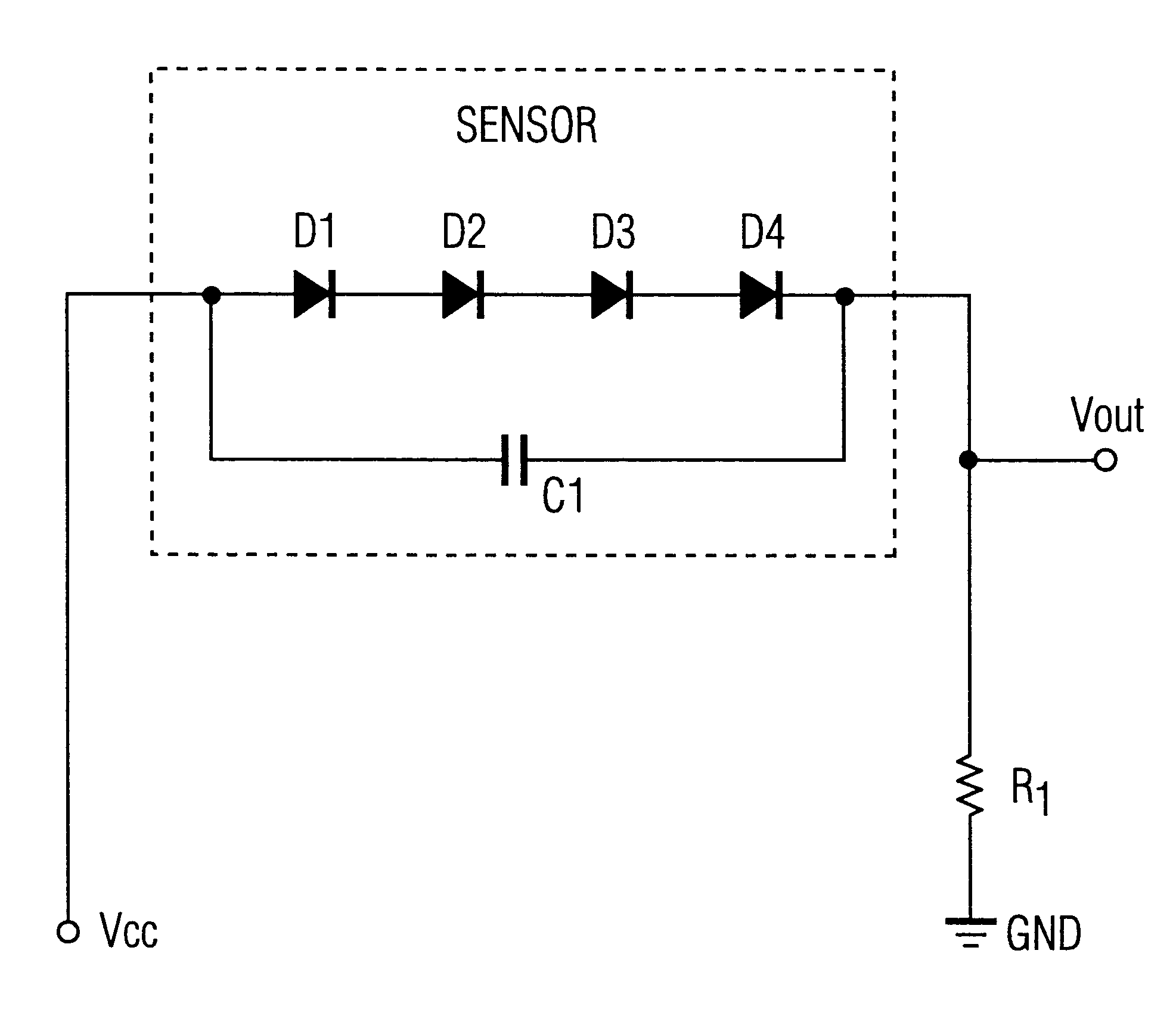
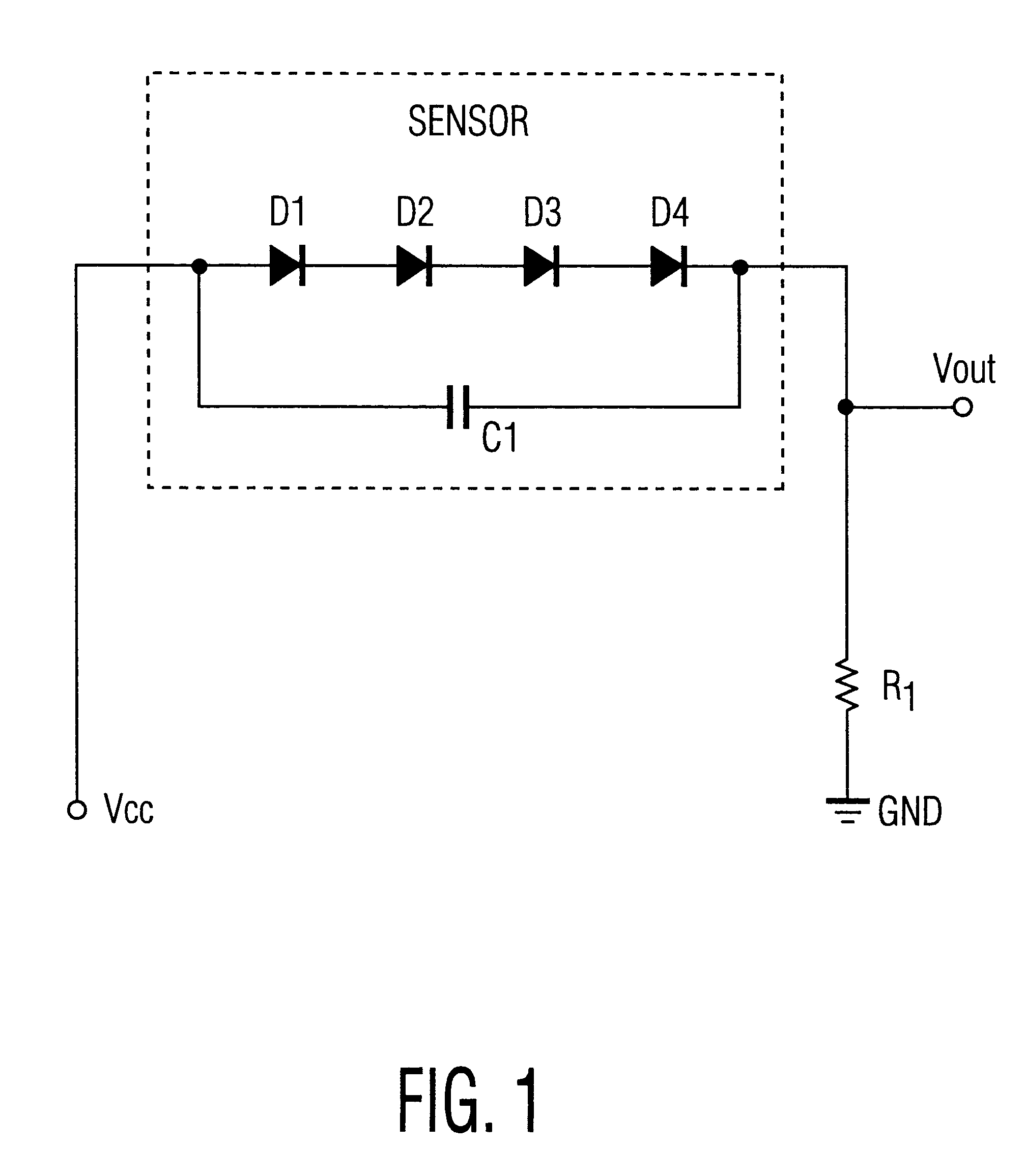
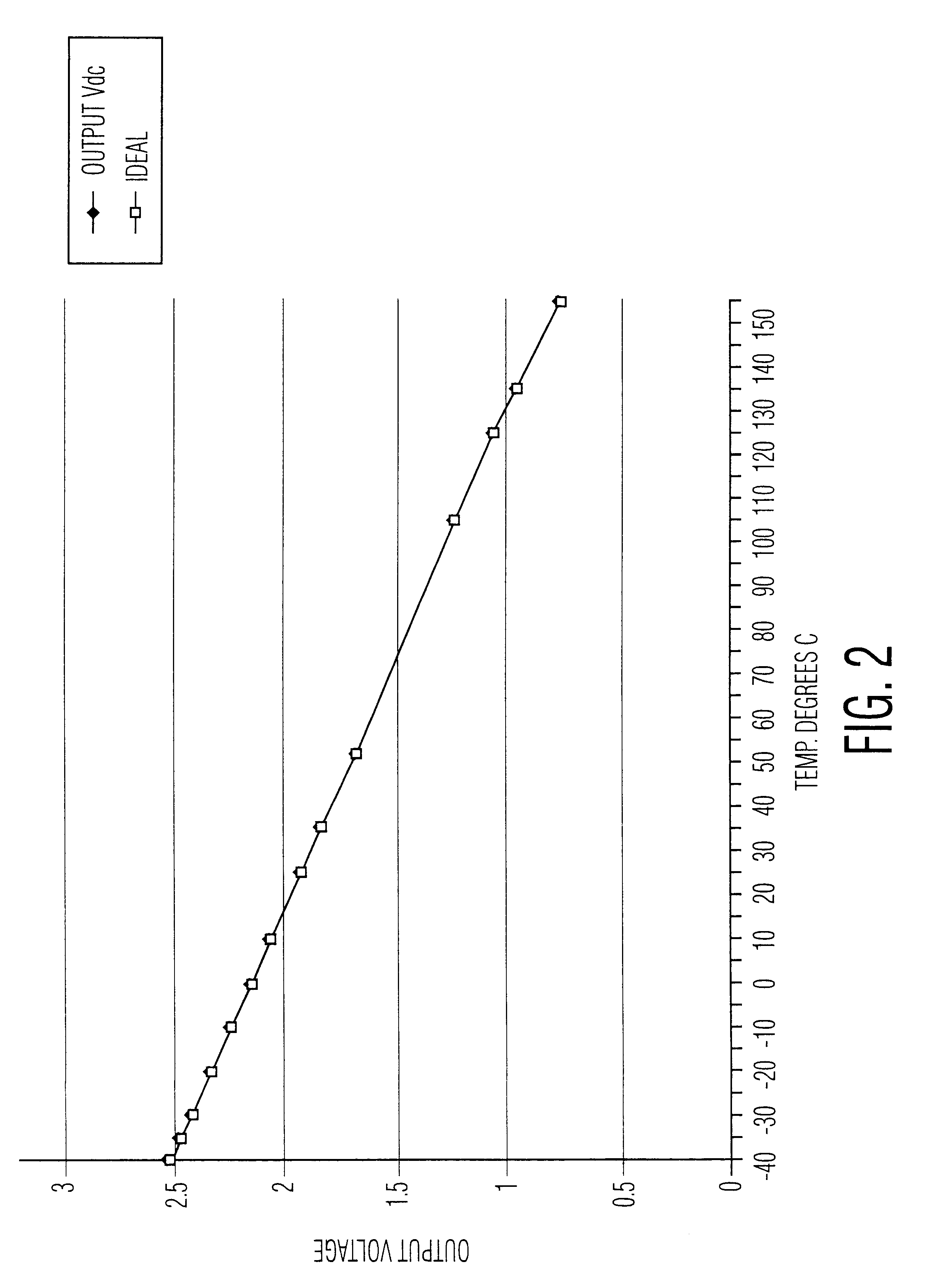
A linear temperature sensor that incorporates passive bipolar semiconductor devices and is capable of high accuracy over a very wide temperature range. The passive bipolar semiconductor device splits a voltage drop between the bipolar semiconductor and a resistor, such that the voltage drop varies approximately linearly in negative dependence on temperature. Optionally the linearity may be improved by providing sufficient current to produce a self-heating effect which compensates for non-linear deviations in performance at low temperatures.

Description

The present invention relates to the field of temperature sensors, and more particularly to temperature sensors based on the intrinsic characteristics of semiconductor devices.BACKGROUND OF INVENTIONThe sensing of temperature is one of the fundamental requirements for environmental control, as well as certain chemical, electrical and mechanical controls. Often, by controlling a process based on a measured temperature, the efficiency or other parameter may be altered, typically to an optimum. However, where the temperature sensor itself is expensive, cumbersome, or requires substantial signal conditioning and processing, these factors weigh heavily against the sensing of every relevant temperature, and rather to employ the minimum number of temperature sensors possible.Thus, the logistical cost of providing and operating the sensor to optimize the operation of the system or process is weighed against the potential gains in system efficiency. Therefore, as the sensor systems become le...

Claims


Application Information

Patent Timeline
Patent Type & Authority Patents(United States)
IPC IPC(8): G01K1/00G01K1/20H01L31/058H01L31/04H01L35/00H01L37/00G01DH10N10/00H10N15/00
CPCG01K7/10
Inventor GOODWIN, SHAUN
Owner AIRPAX
Learn More