

Micro-current facial mask
A micro-current and micro-current power technology, applied in cosmetics, preparations for skin care, and medical devices, etc., can solve the problems of uneven absorption of nutrients, complicated installation and use, etc., and achieve the effect of comprehensive removal of facial skin dirt.
- Summary
- Abstract
- Description
- Claims
- Application Information
AI Technical Summary
Problems solved by technology
Method used
Image

Examples
Embodiment 1
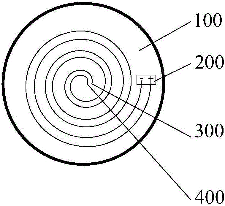
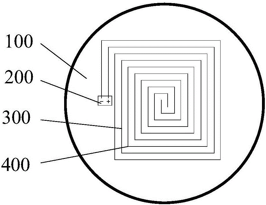
[0091] A kind of micro-current facial mask, comprises facial film body 100, is arranged on a micro-current power supply 200 on the facial mask body 100, the positive electrode conductive strip 300 that is connected with the positive pole of micro-current power supply 200 and the negative electrode conductive strip that is connected with the negative pole of micro-current power supply 200 400; the positive electrode conductive strips 300 are arranged around the first set point in turn around the outer circumference of the first set point; the negative electrode conductive strips 400 are arranged around the second set point around the second set point in turn The outer periphery of the set point; and the positive electrode conductive strip 300 and the negative electrode conductive strip 400 are arranged side by side, so that the positive and negative electrodes are spaced apart.
[0092] In Embodiment 1, the positive electrode conductive strip 300 and the negative electrode condu...
Embodiment 2
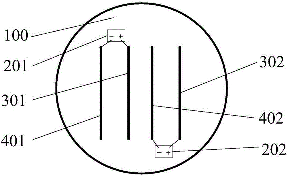
[0098] A kind of micro-current facial mask, comprises facial film body 100, the first micro-current power supply 201 and the second micro-current power supply 202 that are arranged on the facial mask body 100, the first positive electrode conductive strip 301 that is connected with the positive pole of the first micro-current power supply 201, The first negative pole conductive strip 401 connected with the negative pole of the first microcurrent power supply 201, the second positive pole conductive strip 302 connected with the positive pole of the second microcurrent power supply 202, the second negative pole connected with the negative pole of the second microcurrent power supply 202 Conductive strip 402; the positive and negative conductive strips are distributed at positive and negative intervals, such as the first positive conductive strip 301, the first negative conductive strip 401, the second positive conductive strip 302 and the second negative conductive strip 402 from ...
Embodiment 3
[0105] A kind of micro-current facial mask, comprises facial film body 100, the first micro-current power supply 201 and the second micro-current power supply 202 that are arranged on the facial mask body 100, the first positive electrode conductive strip 301 that is connected with the positive pole of the first micro-current power supply 201, The first negative pole conductive strip 401 connected with the negative pole of the first microcurrent power supply 201, the second positive pole conductive strip 302 connected with the positive pole of the second microcurrent power supply 202, the second negative pole connected with the negative pole of the second microcurrent power supply 202 Conductive strip 402; the suspended end of the conductive strip is set at positive and negative intervals, and the angle between the suspended end of the conductive strip and the center of the mask body is ≥ 60°, such as 65°, 70°, 75° , 80°, 85°, 90°, 98°, 110°, 130°, 150°, 180°, etc., (such as ...
PUM
 Abstract
Description
Claims
Application Information