A New Embedded Anti-Blow-by Oil Piston Structure

An oil-piston, anti-channeling technology, applied in the direction of pistons, variable-capacity pump components, liquid-variable-capacity machinery, etc., can solve the problem of increased cost, unfavorable normal use of air compressors or internal combustion engines, and increased friction between the piston and the inner wall of the cylinder liner. Loss and other problems to achieve the effect of solving oil channeling

Active Publication Date: 2018-03-06
FENGHUA DINGLIAN AUTO AIR COMPRESSOR FACTORY
View PDF13 Cites 0 Cited by
  • Summary
  • Abstract
  • Description
  • Claims
  • Application Information

AI Technical Summary

Problems solved by technology

For example, the patent CN102588252A and the patent CN101334021A are improved in terms of materials, so that the sealing ring or the inner wall of the cylinder liner is more wear-resistant, so as to maintain a more durable sealing performance between the piston and the cylinder liner; The structure of the gas ring and / or oil ring is improved to make the sealing effect between the sealing ring and the inner wall of the cylinder liner better to prevent oil blow-by. In short, these solutions all use the "blocking" method to solve the problem, but the actual The use effect is not ideal, and a better effect may be achieved in a short period of time in the early stage, but after a period of operation, the problem remains after the gas ring and oil ring are worn out. And it will also increase; and adopt the "blocking" method, even if the oil leakage problem can be effectively improved, but on the other hand, it will also reduce the amount of oil distribution on the inner wall of the cylinder liner, thereby increasing the friction loss between the piston and the inner wall of the cylinder liner. Conducive to the normal use of air compressors or internal combustion engines

Method used


Image

  • A New Embedded Anti-Blow-by Oil Piston Structure
  • A New Embedded Anti-Blow-by Oil Piston Structure
  • A New Embedded Anti-Blow-by Oil Piston Structure

Examples


Embodiment Construction

[0019] The following descriptions are only preferred embodiments of the present invention, and therefore do not limit the protection scope of the present invention.

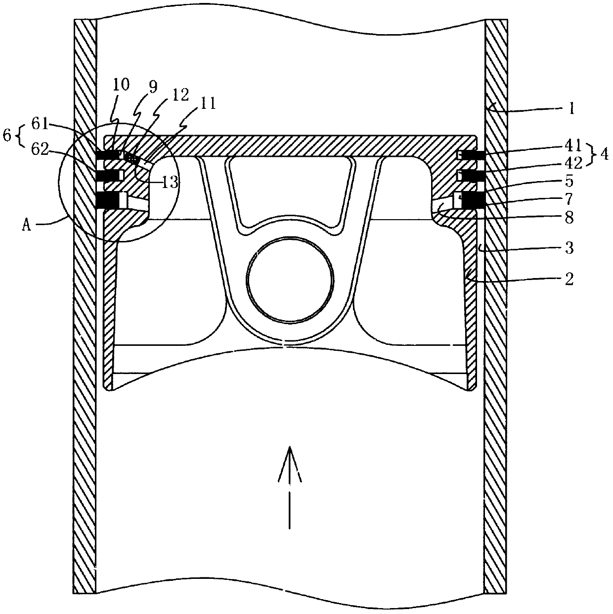
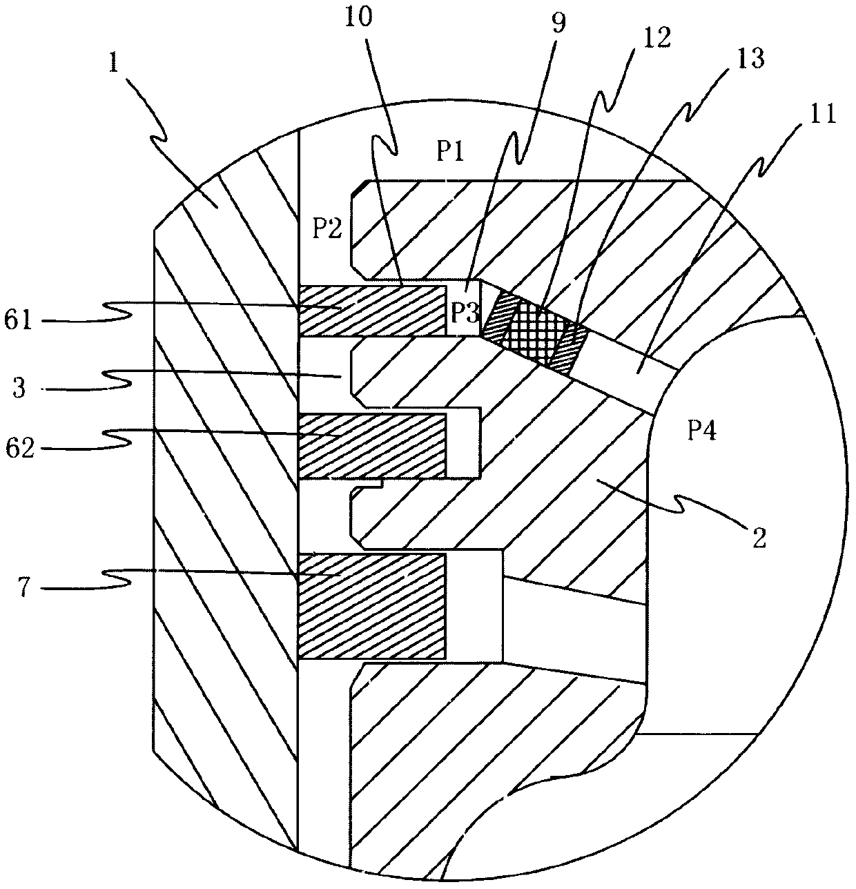
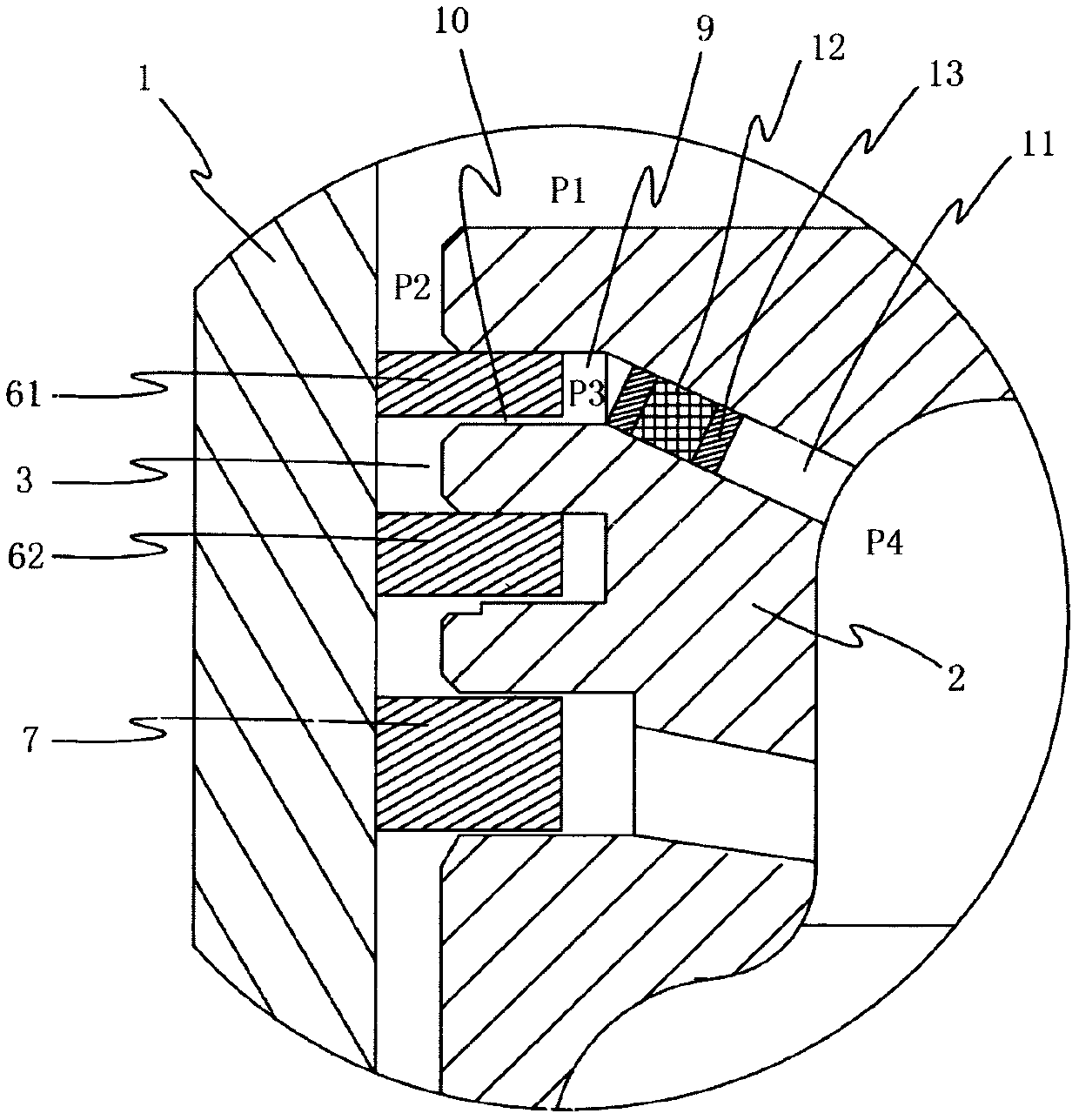
[0020] see Figure 1-Figure 4 , an embedded anti-bleeding piston structure, including a piston 2 arranged in the cylinder liner 1, a gap cavity 3 is provided between the outer wall of the piston 2 and the inner wall of the cylinder liner 1, and an air ring groove is arranged on the outer wall of the piston 2 from top to bottom 4 and the oil ring groove 5, the gas ring groove 4 is equipped with a gas ring 6 that is sealingly matched with the inner wall of the cylinder liner 1, wherein there are two gas ring grooves 4, which are respectively the first gas ring groove 41 and the second gas ring groove The ring groove 42, the first gas ring groove 41 is arranged above the second gas ring groove 42, the first gas ring groove 41 and the second gas ring groove 42 are respectively equipped with a first gas ring 61 and a ...


PUM


Abstract

The invention discloses a novel built-in oil expelling prevention piston structure which comprises a piston arranged in a cylinder sleeve. An interval cavity is formed between the outer wall of the piston and the inner wall of the cylinder sleeve. The outer wall of the piston is provided with a gas ring slot and an oil ring slot. A gas ring is installed in the gas ring slot movably. An oil ring is installed in the oil ring slot. A back clearance cavity is formed between the gas ring and the side wall of the gas ring slot. An interval channel is formed between the gas ring and the upper wall of the gas ring slot and / or the lower wall of the gas ring slot and used for enabling the back clearance cavity and the interval cavity to communicate. A piston body is further provided with an assembly hole. An insert made of powder metallurgy materials is mounted in the assembly hole, and a drainage channel is formed inside the insert. Expelled oil in the back clearance cavity of the piston is removed through the drainage channel and the pressure difference generated during compression of an air compressor or an internal combustion engine, so that the air compressor or the internal combustion engine has a longer service life and operates more stably; and for processing and manufacturing, the demand for precision is low, cost can be reduced, and the novel built-in oil expelling prevention piston structure is beneficial to production, processing and manufacturing.

Description

technical field [0001] The invention belongs to the technical field of air compressors or internal combustion engines, and in particular relates to a novel built-in anti-slipping oil piston structure for air compressors or internal combustion engines. Background technique [0002] For pistons of air compressors or internal combustion engines, the outer wall of the piston is provided with three sealing ring grooves from top to bottom (see patent CN202108699U and patent CN104329239A), which are respectively the first ring groove, the second ring groove and the third ring groove, wherein The first ring groove and the second ring groove are respectively installed with the first air ring and the second air ring which are air-tightly matched with the inner wall of the cylinder liner, and the third oil ring is installed in the third ring groove which is oil-tightly matched with the inner wall of the cylinder liner. The first air ring and the second air ring are used for the air sea...

Claims


Application Information

Patent Timeline
Patent Type & Authority Patents(China)
IPC IPC(8): F04B39/00F02F3/00
CPCF02F3/00F04B39/0005
Inventor 许盛刚
Owner FENGHUA DINGLIAN AUTO AIR COMPRESSOR FACTORY
Why Eureka
Try Eureka