Contact type scanning probe for micro-nano three-coordinate measuring machine

A technology of a three-coordinate measuring machine and a scanning probe, applied in the field of micro-nano testing, can solve the problems of low detection sensitivity and precision of strain gauges, difficult installation and adjustment, etc., and achieves simple structure, good time stability and cost. low effect

Inactive Publication Date: 2016-06-22
ANHUI ELECTRICAL ENG PROFESSIONAL PROFESSIONAL TECHN COLLEGE +3
View PDF5 Cites 21 Cited by
  • Summary
  • Abstract
  • Description
  • Claims
  • Application Information

AI Technical Summary

Problems solved by technology

The existing probe needs to integrate two to four high-precision sensors, which has the problems of complex structure, difficult installation and adjustment, and high cost
For example, the strain gauge-based three-dimensional micro-contact sensing probe developed by the University of Eindhoven in the Netherlands is to make the strain gauge, circuit and elastic elements into an overall structure through precipitation, plate making, etching and other processes. The change of displacement and displacement is detected by the strain gauge installed on the sensitive beam, which is small in size, but the detection sensitivity and accuracy of the strain gauge are relatively low, and the measuring head adopts a triangular topology, which makes the decoupling complicated
The electromagnetic micro-contact probe developed by METAS, the Swiss Federal Bureau of Metrology and Inspection, has three degrees of freedom. The detection in each direction is realized by inductance. The force measurement in the three directions is the same. The structure is mainly made of aluminum. , the electromagnetic probe has a large measurement range, high lateral detection sensitivity and small contact force, but its structure is quite complicated, difficult to install and adjust, and it adopts a triangular suspension structure, which makes decoupling complicated

Method used


Image

  • Contact type scanning probe for micro-nano three-coordinate measuring machine
  • Contact type scanning probe for micro-nano three-coordinate measuring machine
  • Contact type scanning probe for micro-nano three-coordinate measuring machine

Examples


Embodiment Construction

[0028] In this embodiment, the structural form of the contact scanning probe of the micro-nano three-coordinate measuring machine is:

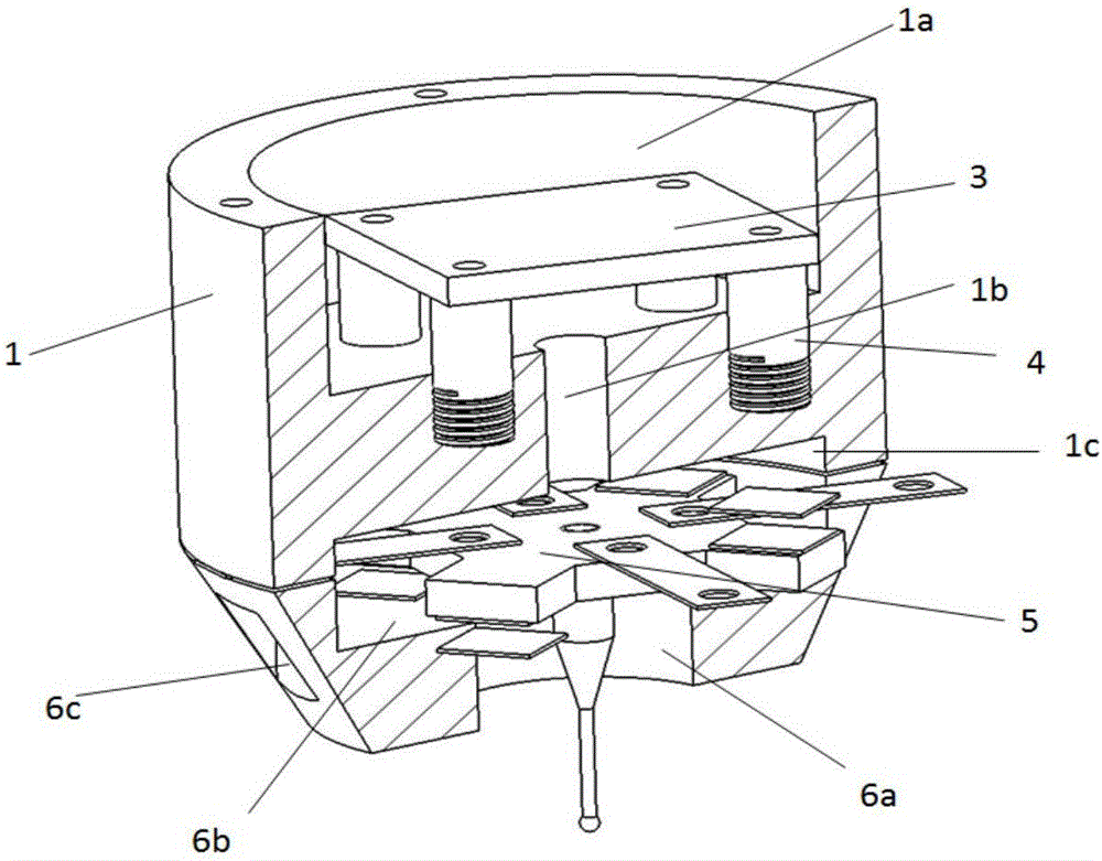
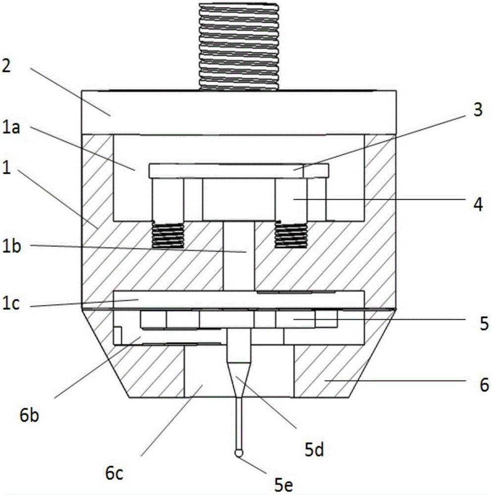
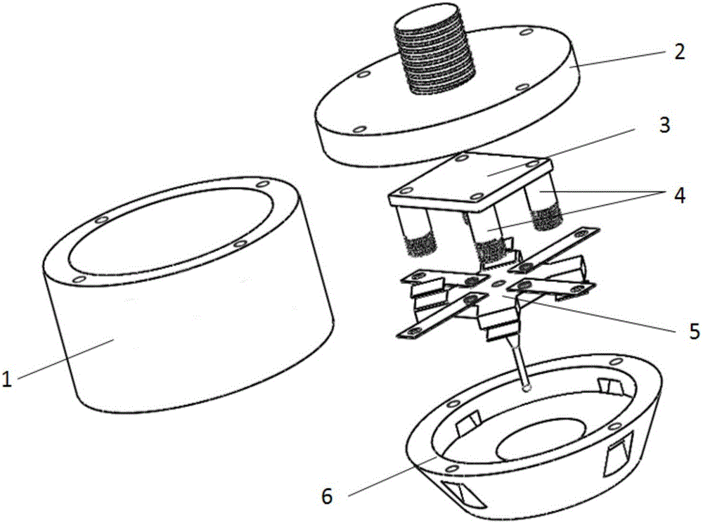
[0029] Such as figure 1 , figure 2 with image 3 As shown, the probe housing is composed of a cylindrical body 1 and a base 6 in the shape of a frustum of a cone received at the bottom of the cylindrical body 1, and a probe unit and a measuring unit are arranged in the probe housing.

[0030] Such as Figure 4 , Figure 5 with Image 6 As shown, the probe unit is provided with a suspension piece 5a in the shape of a "ten" in the inner cavity 6b of the base 6, and cantilever springs are respectively connected to the top surface of the suspension piece 5a and the angle between adjacent cantilevers. sheet 5b, the other end of the cantilever reed 5b is connected to the top annular end face of the base 6, forming the suspension structure of the suspension sheet 5a in the inner cavity of the base 6; The probe 5d of the ruby ​​measuring ball 5...


PUM


Abstract

The invention discloses a contact type scanning probe for a micro-nano three-coordinate measuring machine. The contact type scanning probe is characterized in that a measuring head and a measuring unit are arranged in a probe housing. The measuring head unit comprises a suspension sheet (5a) and a base (6), wherein the suspension sheet (5a) is arranged inside the inner cavity of the base (6) to form a suspension structure. The central through hole of the suspension sheet is fixedly provided with a probe with a measuring ball. The probe extends out of the bottom port of the base and is free from swinging under the interference of the bottom port of the base. The measuring unit comprises a capacitive sensor arranged on each cantilever of the suspension sheet. According to the technical scheme of the invention, the output signal of the capacitive sensor is adopted as the detection signal of the probe. Therefor, the detection result is ensured to be high in accuracy, high in sensitivity and small in measurement force. Meanwhile, the contact type scanning probe is high in stability and low in cost.

Description

technical field [0001] The invention relates to the field of micro-nano testing, more specifically a contact-scanning three-dimensional probe applied to a nanometer three-coordinate measuring machine for sensing the three-dimensional shape of the surface of an object. Background technique [0002] In recent years, the rapid development of microelectronics technology has triggered a revolution in miniaturization, especially the development of processing technology for MEMS devices, and various micro-nano-level tiny devices have emerged, such as micro-gears, micro-holes, Micro nozzles, micro steps and other MEMS products. The processing accuracy of these micro-devices is on the order of micro-nano, so it is necessary to develop special high-precision detection methods and technical means to carry out precise measurement of these micro-devices. For this reason, relevant institutions in various countries are devoting themselves to the research of three-coordinate measuring mach...

Claims


Application Information

Patent Timeline
Patent Type & Authority Applications(China)
IPC IPC(8): G01B7/012G01B7/016
CPCG01B7/012G01B7/016
Inventor 李瑞君周斌程琳程真英陈晶
Owner ANHUI ELECTRICAL ENG PROFESSIONAL PROFESSIONAL TECHN COLLEGE
Why Eureka
Try Eureka