A micro-stressed support structure for large-aperture mirrors

A large-diameter mirror and support structure technology, applied in the field of optical engineering, can solve the problems of difficult to eliminate or reduce the surface shape of the optical components of the system, the failure of the performance indicators of the optical system, and the influence of the surface shape accuracy of the reflector, so as to reduce defects. Effect, easy assembly, simple structure effect

Active Publication Date: 2018-02-27
XI'AN INST OF OPTICS & FINE MECHANICS - CHINESE ACAD OF SCI
View PDF4 Cites 0 Cited by
  • Summary
  • Abstract
  • Description
  • Claims
  • Application Information

AI Technical Summary

Problems solved by technology

Thermal changes and vibrations caused by the surrounding environment of the optical system, as well as the assembly stress brought by the traditional support structure, have a direct impact on the surface shape of the mirror, and the surface shape of the mirror is directly related to the optics. The performance index of the system, so if there is a problem with the support structure of the mirror, it will cause the performance index of the optical system to fail, or even make the optical system scrapped
[0003] For reflectors with a diameter of less than 600mm, rigid support is traditionally used, and the axial end of the reflector is axially fixed by a pressure ring. It is difficult to eliminate or reduce the thermal deformation of the optical components of the system and the vibration of the optical system. The pressure ring is easy to cause over-positioning of the reflector, which in turn affects the surface accuracy of the reflector

Method used


Image

  • A micro-stressed support structure for large-aperture mirrors
  • A micro-stressed support structure for large-aperture mirrors
  • A micro-stressed support structure for large-aperture mirrors

Examples


Embodiment Construction

[0025] The present invention will be described in detail below in conjunction with the accompanying drawings and specific embodiments.

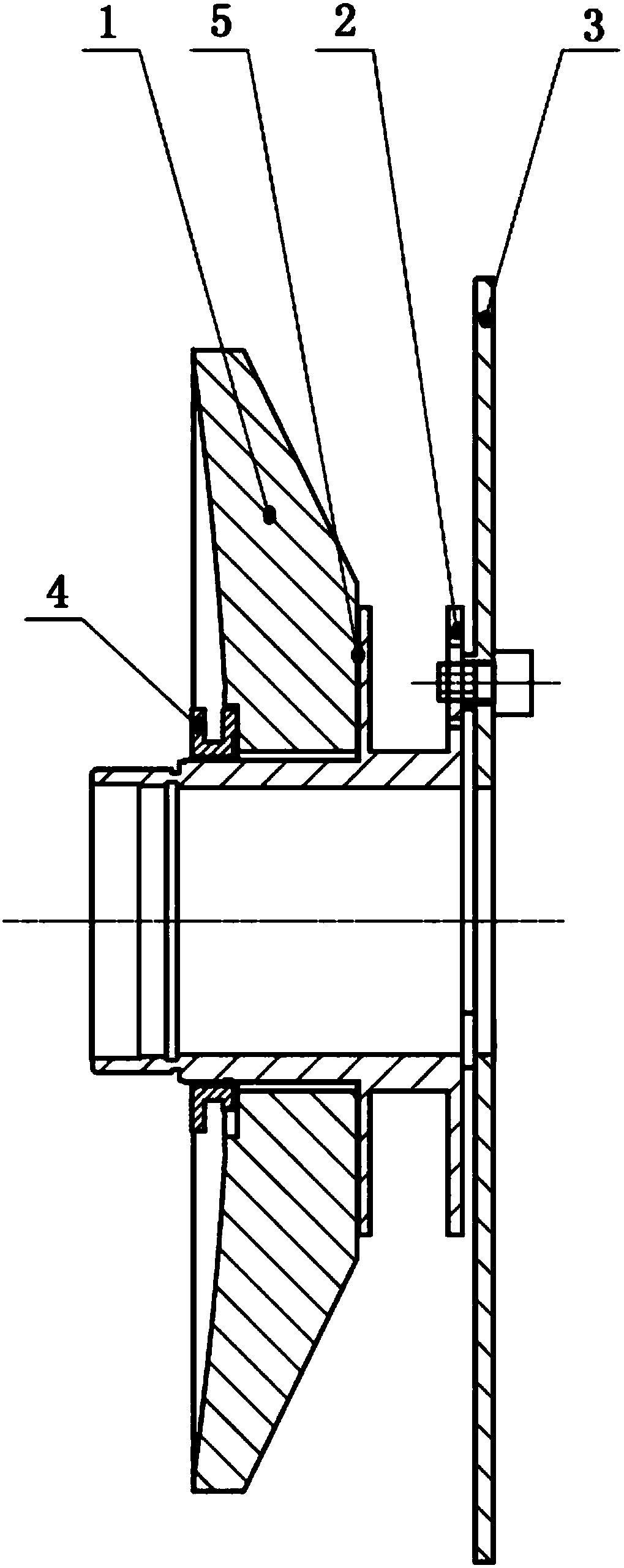
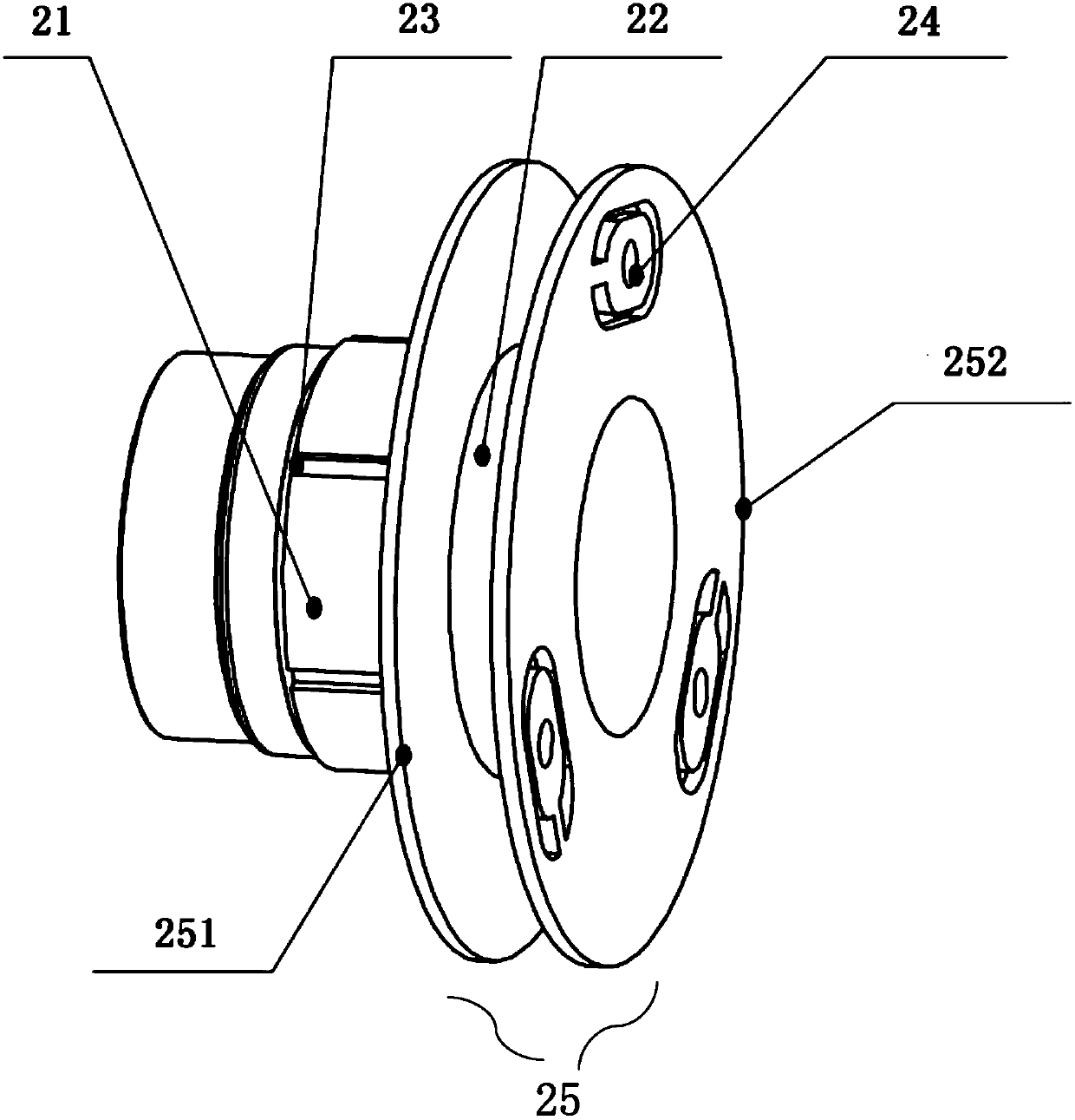
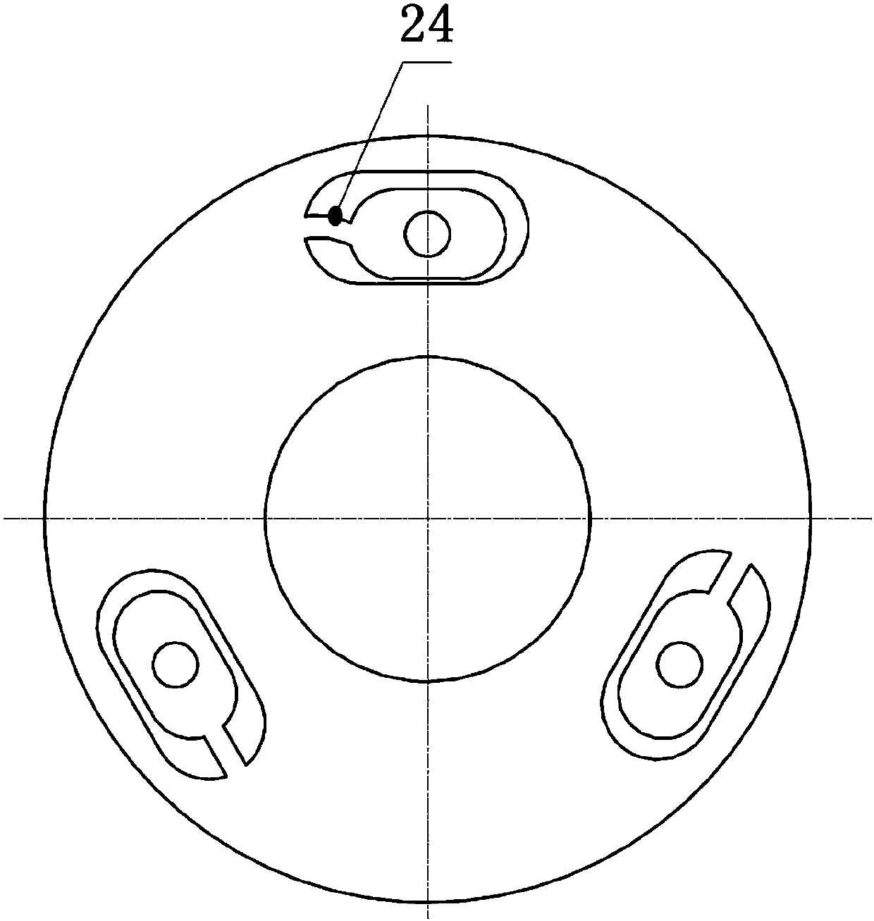
[0026] Such as figure 1 , figure 2 with image 3 As shown, the micro-stress support structure of the large-diameter mirror provided by the present invention includes a large-diameter mirror 1 , a mirror holder 2 and an optical system base plate 3 . The mirror base 2 is made of a metal material or a composite material with a low coefficient of thermal expansion, and it includes a mirror base base plate 25 and a mirror base central axis 21; the mirror base base plate 25 includes a front end base plate 251 and a rear end base plate 252. The first stress relief grooves 22 are provided between the end base plates 252 ; the central axis 21 of the mirror base is a stepped axis, and a plurality of second stress relief grooves 22 are provided in the area matching with the large-aperture mirror 1 .

[0027] When assembling, pass the central axis 21...


PUM


Abstract

The invention belongs to the field of optics and provides a micro-stress support structure for a large-diameter reflector, aiming at solving the problem that the traditional support structure is difficult to ensure the surface shape of the reflector. The invention includes a large-diameter reflector, a mirror base, an axial fastening pressure ring and an optical system base plate, wherein the mirror base includes a mirror base base plate and a mirror base central axis, and the mirror base base plate includes a front end base plate and a rear end base plate; the axial fastening The follower ring consists of an inner and outer ring with multiple tabs. Stress relief grooves are arranged between the front end base plate and the rear end base plate, on the central axis of the mirror holder, and between the inner ring and the outer ring. When assembling, the central axis of the mirror base passes through the center hole of the large-diameter reflector to form a clearance fit, the bottom of the large-diameter reflector is close to the bottom plate of the front end of the mirror base, and the other end of the large-diameter reflector is fastened by an axial fastening pressure ring Positioning, the bottom plate at the rear end of the mirror base is connected with the bottom plate of the optical system through a flexible hinge. The invention can effectively guarantee the surface shape precision of the reflecting mirror, and has the advantages of simple structure and easy assembly.

Description

technical field [0001] The invention belongs to the field of optical engineering, and relates to a micro-stress support structure of a large-diameter reflector, where the large-diameter reflector refers to a reflector with a diameter of ≤600mm. Background technique [0002] At present, in the field of optical engineering, especially in the development of large-aperture optical systems, the supporting structure of large-aperture mirrors has become the focus of research. Thermal changes and vibrations caused by the surrounding environment of the optical system, as well as the assembly stress brought by the traditional support structure, have a direct impact on the surface shape of the mirror, and the surface shape of the mirror is directly related to the optics. The performance index of the system, so if there is a problem with the support structure of the mirror, it will cause the performance index of the optical system to fail, or even make the optical system scrapped. [0...

Claims


Application Information

Patent Timeline
Patent Type & Authority Patents(China)
IPC IPC(8): G02B7/183
CPCG02B7/183
Inventor 刘阳林上民王灵光刘杰王虎薛要克刘美莹陈苏杨少东
Owner XI'AN INST OF OPTICS & FINE MECHANICS - CHINESE ACAD OF SCI
Why Eureka
Try Eureka