

Data transmission method and system
A data sending method and data packet technology, applied in the field of communication, can solve the problem that the wireless communication system cannot meet the higher delay and reliability requirements of new business applications
- Summary
- Abstract
- Description
- Claims
- Application Information
AI Technical Summary
Problems solved by technology
Method used
Image

Examples
Embodiment 1
[0187] Embodiment 1: PDCP PDU redundant transmission under carrier aggregation (CA).
[0188] In the carrier aggregation scenario, multiple carriers provide wireless transmission for the same UE, and each carrier corresponds to a cell. see Figure 7 , the following is an example where different cells used for carrier aggregation belong to one base station.
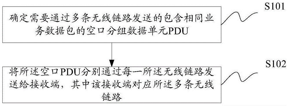
[0189] The downlink transmission in this embodiment includes:
[0190] Step 1: The base station receives the data packet from the upper layer, allocates the PDCPSN, organizes the PDCP PDU, and maintains a PDCPdiscardtimer for each PDCP PDU;
[0191] Step 2: The base station maps the same PDCP PDU to cell 1 and cell 2 for simultaneous transmission;
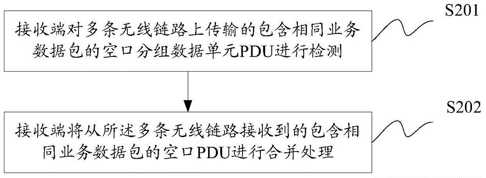
[0192] Step 3: The UE receives PDCP PDUs from cell 1 and cell 2 respectively, performs duplicate detection and sorting according to the PDCP SN of the received PDCP PDUs, and submits the correctly received PDCP PDUs to the upper layer.
[0193] Step 4: UE generates a header...
Embodiment 2
[0199] Embodiment 2: Redundant transmission of PDCP PDUs under the dual connection 1A architecture.
[0200] Dual connectivity means that the UE maintains connection with two cells, generally a macro cell (corresponding to MeNB) and a small cell (corresponding to SeNB). Dual connectivity 1A architecture such as Figure 8 shown.
[0201] The downlink transmission in this embodiment includes:
[0202] Step 1: One of the base stations, such as the macro cell base station (MeNB) or the centralized processing entity receives the data packet from the upper layer, allocates the PDCPSN, organizes the PDCP PDU, and maintains a PDCPdiscardtimer for each PDCP PDU;
[0203] Step 2: PDCP PDU organizes the base station, for example, the macro cell base station (MeNB) forwards the organized PDCP PDU or (PDCPSN+ data packet) to another base station, and the macro cell base station corresponds to the small cell base station (SeNB), or
[0204] The centralized processing entity sends the org...
Embodiment 3
[0213] Embodiment 3: PDCP PDU redundant transmission under the dual connection 3C architecture.
[0214] see Figure 9 , under the dual connectivity 3C architecture, the PDCP layer is only located in the MeNB, which is more convenient for the multi-channel transmission operation in the embodiment of the present invention.
[0215] The downlink transmission in this embodiment includes:
[0216] Step 1: The macro cell base station (MeNB) receives the data packet from the upper layer, allocates the PDCPSN, organizes the PDCP PDU, and maintains a PDCPdiscardtimer for each PDCP PDU;
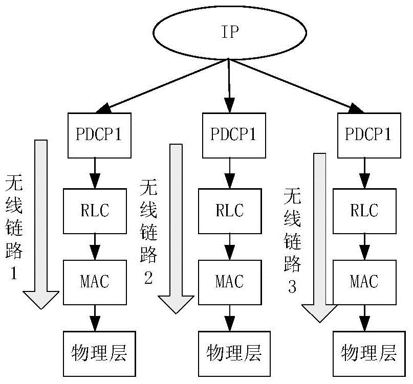
[0217] Step 2: The macro cell base station (MeNB) maps the organized PDCP PDU to two PDCP layer entities;
[0218] Step 3: The macro cell and the small cell transmit the organized PDCP PDU at the same time and start the PDCP discard timer, and the PDCP layer entity of the small cell needs to send the PDCP PDU to the lower layer of the small cell;
[0219] Step 4: The UE receives PDCP PDUs from the ...
PUM
 Abstract
Description
Claims
Application Information