Filter drier

A technology of filter drier and desiccant, which is applied in the field of pollutant control, can solve problems such as adverse effects on system performance and endanger the service life of the system, and achieve the effects of low material cost, shortened manufacturing time, and reduced size and weight

Inactive Publication Date: 2016-06-22
PARKER HANNIFIN CORP
View PDF5 Cites 0 Cited by
  • Summary
  • Abstract
  • Description
  • Claims
  • Application Information

AI Technical Summary

Problems solved by technology

Over time, elevated levels of these contaminants can jeopardize the useful life of the system and adversely affect system performance

Method used


Image

  • Filter drier
  • Filter drier
  • Filter drier

Examples


Embodiment Construction

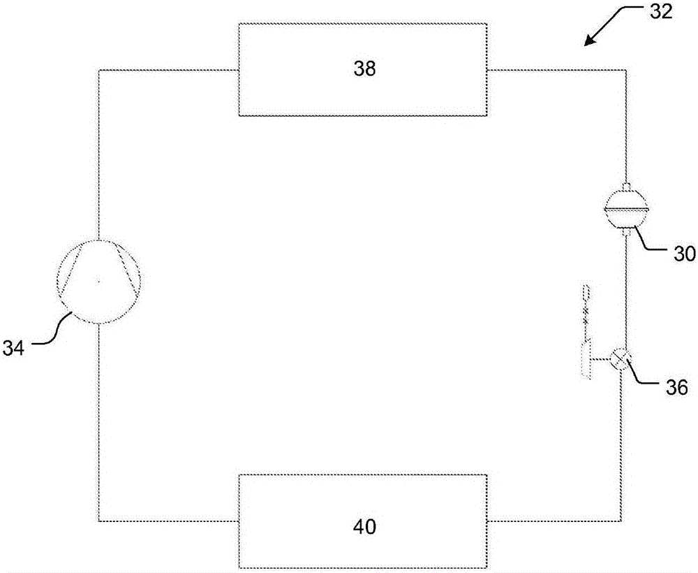
[0032] figure 2 is a schematic diagram of a spherical filter drier 30 as a component of an HVACR system 32 together with other HVACR components such as compressor 34 , expansion unit 36 ​​, condenser 38 and evaporator 40 . This system is exemplary only and it should be understood that the filter drier can be installed as a component in a variety of HVACR systems including those with figure 2 Parts that are the same as or different from those shown.

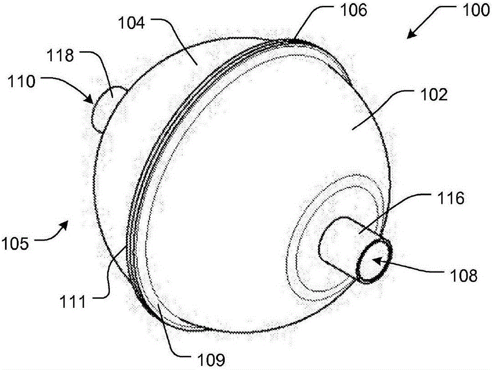
[0033] A specific embodiment of a spherical filter drier 100 is shown in Figure 3-5 middle. The filter drier is generally spherical in shape and may be formed from a pair of generally hemispherical first and second housings 102, 104 coupled to each other at a joint 106 to form a substantially spherical housing 105 having a substantially spherical cavity 107 . The two hemispherical shells may include respective flange portions 109 , 111 , which may be joined together to form the spherical shell 105 by welding, brazing or oth...


PUM


Abstract

A spherical filter drier for an HVACR system includes a generally spherical shell and a core that is fixed position relative to the shell. The shell has a first opening and a second opening in fluid communication with one another across the core. The core includes a media that removes contaminants from fluid flowing from the first opening through the core to the second opening. The spherical shell may be a monolithic shell, or formed from a pair of generally hemispherical shells.

Description

[0001] Related patent data [0002] This application claims priority to US Provisional Application No. 61 / 895,186, filed October 24, 2013, the entire contents of which are incorporated herein by reference. technical field [0003] The present invention relates to pollutant control in heating, ventilation, air conditioning and refrigeration (HVACR) systems. Background technique [0004] The function of a filter drier in an HVACR system is to remove harmful contaminants such as moisture, acids, copper oxides, metal flakes, waxy compounds, etc. Over time, elevated levels of these contaminants can jeopardize the useful life of the system and adversely affect system performance. [0005] Historically, conventional filter-driers have been generally cylindrical in shape, such as filter-drier 10 in FIG. 1 . Such filter-driers typically include a tubular housing 12 closed by a pair of end caps 14 and 16, each of which forms a respective fitting 18 and 20 and a potential leak path ...

Claims


Application Information

Patent Timeline
Patent Type & Authority Applications(China)
IPC IPC(8): F25B43/00
CPCF25B43/003B01D53/02B01D2253/342B01D2257/80
Inventor 克里斯多夫·里夫斯大卫·德纳马修·斯达菲尔德丹尼尔·斯托达德卡罗尔·马夸特
Owner PARKER HANNIFIN CORP
Why Eureka
Try Eureka