Automobile headlamp assembly and automobile headlamp

A technology for automobile headlights and components, which is applied in the directions of headlights, vehicle parts, and components of lighting devices, etc., can solve the problems of vehicle visual interference, large beam divergence angle, and difficulty in cost and appearance.

Active Publication Date: 2016-06-29
重庆佧爱光电科技有限公司
View PDF6 Cites 13 Cited by
  • Summary
  • Abstract
  • Description
  • Claims
  • Application Information

AI Technical Summary

Problems solved by technology

[0002] Car headlights are an essential part of the car. The current car headlights usually use a single bulb placed at the focus of the parabolic reflector for night lighting. Since the light source has a certain size, it can be reflected by a certain size. It is difficult to effectively control the collimation of the beam behind the cup, and the divergence angle of the beam is relatively large, so there will be insufficient light at a certain distance in the distance; the current negative way is to increase the power of the bulb to solve this problem, which will affect the control and use of the system. Life, environmental protection and safety will bring disadvantages. The more important problem is that the light intensity outside the effective lighting range will be greatly increased, which will cause great visual interference to oncoming vehicles and easily cause traffic accidents. This phenomenon is well known.
If multiple groups of light bulbs are used for lighting, although the problems of insufficient brightness and short irradiation distance can be solved, it is difficult to meet the requirements in terms of cost and appearance. The increase of the beam will inevitably lead to the increase of the divergence angle of the beam. With the continuous development of LED technology, it is believed that the LED light source with high power and small size will gradually be improved to a certain extent, but this improvement is limited after all. The huge advantages of LED light source are well known. It is widely used in automobiles at present, but there are still many technical problems in the application of headlights. Therefore, the development of LED light sources and lighting optical path systems for headlights has always been a hot spot in this field. and puzzles

Method used


Image

  • Automobile headlamp assembly and automobile headlamp
  • Automobile headlamp assembly and automobile headlamp
  • Automobile headlamp assembly and automobile headlamp

Examples


Embodiment 1

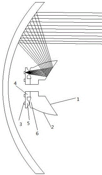
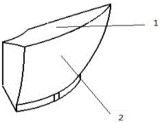
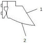
[0033] Such as Figures 1 to 6 As shown, the present invention discloses an automobile headlight assembly, which includes a light source, a condenser lens group and a light control lens mechanism, the condenser lens group is located between the light source and the light control lens mechanism; the light control lens The mechanism includes a reflection surface 1 that only reflects the light beam, and an exit surface 2 that refracts the light beam reflected by the reflection surface 1; the reflection surface 1 cooperates with the exit surface 2, so that the light beam generated by each light source is reflected The virtual image points formed behind the surface 1 and the exit surface 2 are all at the same position on the geometric central axis of the light control lens mechanism.

[0034] The condensing lens group includes a first condensing lens group and a second condensing lens group juxtaposed to each other; the first condensing lens group is arranged on the lens seat 4, an...

Embodiment 2

[0045] This embodiment is substantially the same as Embodiment 1, the difference is that: the condensing lens group includes a first condensing lens group and a second condensing lens group juxtaposed to each other; the first condensing lens group and the second condensing lens group The two light-condensing lens groups are all arranged on the lens seat 4 .

[0046] The first condensing lens group includes several first curved lenses 5 that are evenly arranged in a circular array on the lens holder 4, and the second condensing lens group includes a number of second curved lenses 6 that are evenly arranged in a circular array on the lens holder 4. Above, the first curved lens 5 and the second curved lens 6 are matched with each other and located on the same axis.

[0047] The light control lens mechanism includes a concave reflective surface 1 located in the middle, an outgoing surface 2 located on the side, and a bottom surface. The outgoing surface 2 is connected to the refle...

Embodiment 3

[0049] Such as Figure 5 As shown, this embodiment is substantially the same as Embodiments 1 and 2, except that the reflective surface 1 is spliced ​​by several fan-shaped / fan-shaped reflective units 7; wherein the reflective unit 7 is the same as the LED light source 3, the second A curved lens 5 and a second curved lens 6 are matched.

[0050] Since the reflective surface is spliced ​​by several fan-shaped / fan-shaped reflective units, the reflection is no longer continuous. Each fan-shaped / fan-shaped reflective unit reflects the beam to a designated area, which can facilitate the adjustment of the beam. Concentrating the light beam is convenient for adjusting the uniformity of brightness; each fan-shaped / fan-shaped reflective unit corresponds to each LED light source, and each fan-shaped / fan-shaped reflective unit reflects the light beam emitted by the corresponding LED light source.


PUM


Abstract

The invention relates to the optical field, in particular to an automobile headlamp assembly and an automobile headlamp. The automobile headlamp assembly comprises a light source, a condensing lens set and a light control lens mechanism; the condensing lens set is located between the light source and the light control lens mechanism; the light control lens mechanism comprises a reflecting surface only reflecting a light beam and an emergent surface refracting the light beam obtained after being reflected by the reflecting surface; the automobile headlamp comprises a paraboloid reflection cup and the automobile headlamp assembly, and the automobile headlamp assembly is arranged in the paraboloid reflection cup; and the light beam sent out by the light source is gathered to the reflecting surface through the condensing lens set, and the light beam reflected by the reflecting surface is refracted to the inner wall of the paraboloid reflection cup from the emergent surface and then is shot to the distance place. The automobile headlamp assembly can gather light, irradiation of the light towards one direction is facilitated, and the enough irradiation brightness is ensured. According to the automobile headlamp, uniform distribution of the light beam can be achieved, the light beam is irradiated in a long-distance manner, the light beam cannot be diverged in the long-distance irradiation, brightness is uniform, and the strength is high.

Description

technical field [0001] The invention relates to the field of optical lenses, in particular to an automobile headlight assembly and the automobile headlight. Background technique [0002] Car headlights are an essential part of the car. The current car headlights usually use a single bulb placed at the focus of the parabolic reflector for night lighting. Since the light source has a certain size, it can be reflected by a certain size. It is difficult to effectively control the collimation of the beam behind the cup, and the divergence angle of the beam is relatively large, so there will be insufficient light at a certain distance in the distance; the current negative way is to increase the power of the bulb to solve this problem, which will affect the control and use of the system. Life, environmental protection and safety will bring disadvantages. The more important problem is that the light intensity outside the effective lighting range will be greatly increased, which will...

Claims


Application Information

Patent Timeline
Patent Type & Authority Applications(China)
IPC IPC(8): F21S8/10F21V5/04F21V19/00F21W101/02F21W101/10F21Y115/10F21Y105/18F21W107/10
CPCF21S41/141F21S41/265F21W2102/00F21W2107/10
Inventor 曹红曲李健雄
Owner 重庆佧爱光电科技有限公司
Why Eureka
Try Eureka