
Ultrasonic detection method for thick-walled tube girth weld surface defect diffraction time difference

A technology of diffraction time difference and ultrasonic detection, which is used in the analysis of solids using sonic/ultrasonic/infrasonic waves, material analysis using sonic/ultrasonic/infrasonic waves, measurement devices, etc. and other problems, to achieve the effect of improving defect signal-to-noise ratio, improving detection sensitivity and good detection effect.

Active Publication Date: 2016-06-29
ELECTRIC POWER RES INST STATE GRID JIANGXI ELECTRIC POWER CO +1
View PDF3 Cites 5 Cited by
  • Summary
  • Abstract
  • Description
  • Claims
  • Application Information

AI Technical Summary

Problems solved by technology

Therefore, when testing the surface of the girth weld of large-diameter thick-walled pipes, in order to ensure proper sensitivity, the gain of the testing equipment has to be greatly increased, resulting in a corresponding increase in the amplitude of the interference signal and a decrease in the signal-to-noise ratio of the defect signal. small, making identification difficult
Especially for defects with point-like defect characteristics, such as circular pores, transverse cracks, etc., their signals can be completely obliterated by interference signals and cannot be identified, resulting in missed detection

Method used


Image

  • Ultrasonic detection method for thick-walled tube girth weld surface defect diffraction time difference
  • Ultrasonic detection method for thick-walled tube girth weld surface defect diffraction time difference
  • Ultrasonic detection method for thick-walled tube girth weld surface defect diffraction time difference

Examples


Embodiment Construction

[0026] The technical solutions of the present invention will be further described below in conjunction with the accompanying drawings and embodiments.

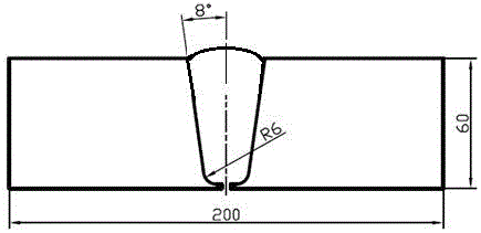
[0027] See attached Figure 7 , a method for diffraction time-of-flight ultrasonic testing of surface defects in girth welds of thick-walled pipes, the steps of the ultrasonic testing method are as follows:

[0028] (1) Make a comparison test block made of Q235-A;

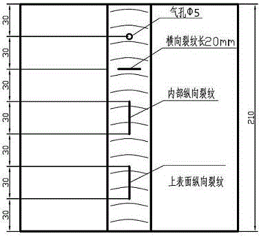
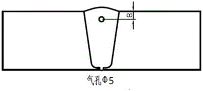
[0029] The length, width, and height of the comparison test block in this example are 210mm×200mm×60mm. There is a weld seam in the center of the test block. There are four simulated defects in the weld, which are Φ5mm pores, 20mm long transverse cracks, internal longitudinal cracks and upper surface longitudinal cracks, and these defects are evenly distributed in the length direction of the test block.

[0030] (2) Place two shear wave oblique probes (transmitting probe 1 and receiving probe 2) symmetrically on the outer surface of the base metal on both sides o...


PUM

PropertyMeasurementUnit
Thicknessaaaaaaaaaa
Outer diameteraaaaaaaaaa

Abstract

The invention provides an ultrasonic detection method for the thick-walled tube girth weld surface defect diffraction time difference. The method includes the steps that firstly, a reference block weld is detected, and arranged simulated defects are verified to be detected; then two transverse wave angle probes, namely, the transmitting probe (1) and the receiving probe (2) are symmetrically placed on the outer surfaces of base metal on the two sides of a detected thick-walled tube girth weld (3), the center distance between the probes is adjusted to be proper to adjust lateral waves to 40% to 80% of the full screen height, and the detected thick-walled tube girth weld is detected in a non-parallel scanning mode. The 65-degree transverse wave angle probes are adopted for detection, compared with an existing detection method, energy loss of the probes is small, and detection sensitivity is greatly improved. The detection rate of defects such as round air holes and transverse cracks with dot-shaped defect characteristics can be remarkably improved, wherein the defects are formed on the surface layer of the weld. The detection method cannot be disturbed by various deformation waves of bottom waves.

Description

technical field [0001] The invention relates to a diffraction time-difference ultrasonic detection method for surface defects of thick-walled pipe girth welds, belonging to the technical field of ultrasonic detection of welds. Background technique [0002] Diffraction time-of-flight ultrasonic testing has unique technical advantages compared with traditional ultrasonic testing methods. With the formulation and release of relevant technical standards for diffractive time-of-flight ultrasonic testing, the diffractive time-of-flight ultrasonic testing technology has been widely used in China. In the field of electric power industry, with the continuous development of boilers for thermal power generating units in the direction of high parameters and large capacity, large-diameter thick-walled tubes have been used more and more. The thickness of these pipes can exceed 60 mm, and as the pipe wall thickness increases, the weld reinforcement also widens, and the width of the reinfor...

Claims


Application Information

Patent Timeline
IPC IPC(8): G01N29/04
CPCG01N29/041G01N2291/023
Inventor 魏东斌
Owner ELECTRIC POWER RES INST STATE GRID JIANGXI ELECTRIC POWER CO
Learn More