
A device for simulating the migration and transformation of soil water and fertilizer under different plow layer structures

A technology of migration and transformation, soil water, applied in the direction of measuring devices, soil material testing, instruments, etc., can solve the problems that the soil column device cannot dynamically monitor the dynamic changes of soil moisture for a long time, cannot monitor the nutrients, and the ecosystem is not an ecosystem, etc., to achieve Achieve long-term dynamic monitoring, reduce test cost, and improve test accuracy

Active Publication Date: 2018-03-20
INST OF AGRI RESOURCES & REGIONAL PLANNING CHINESE ACADEMY OF AGRI SCI
View PDF6 Cites 0 Cited by
  • Summary
  • Abstract
  • Description
  • Claims
  • Application Information

AI Technical Summary

Problems solved by technology

[0005] 1. Most of the current soil column experiments are carried out in an ideal environment without crops, but the existence of crops plays an important role in the migration and transformation of water and nutrients. An ecosystem without crops is not a complete ecosystem
[0006] 2. The traditional soil column test cannot achieve all-round monitoring of nutrient leaching, crop absorption, greenhouse gas emissions, etc.
[0007] 3. The traditional soil column device cannot dynamically monitor the dynamic changes of soil moisture at different levels for a long time and extract the leaching solution at different soil levels

Method used


Image

  • A device for simulating the migration and transformation of soil water and fertilizer under different plow layer structures

Examples


Embodiment

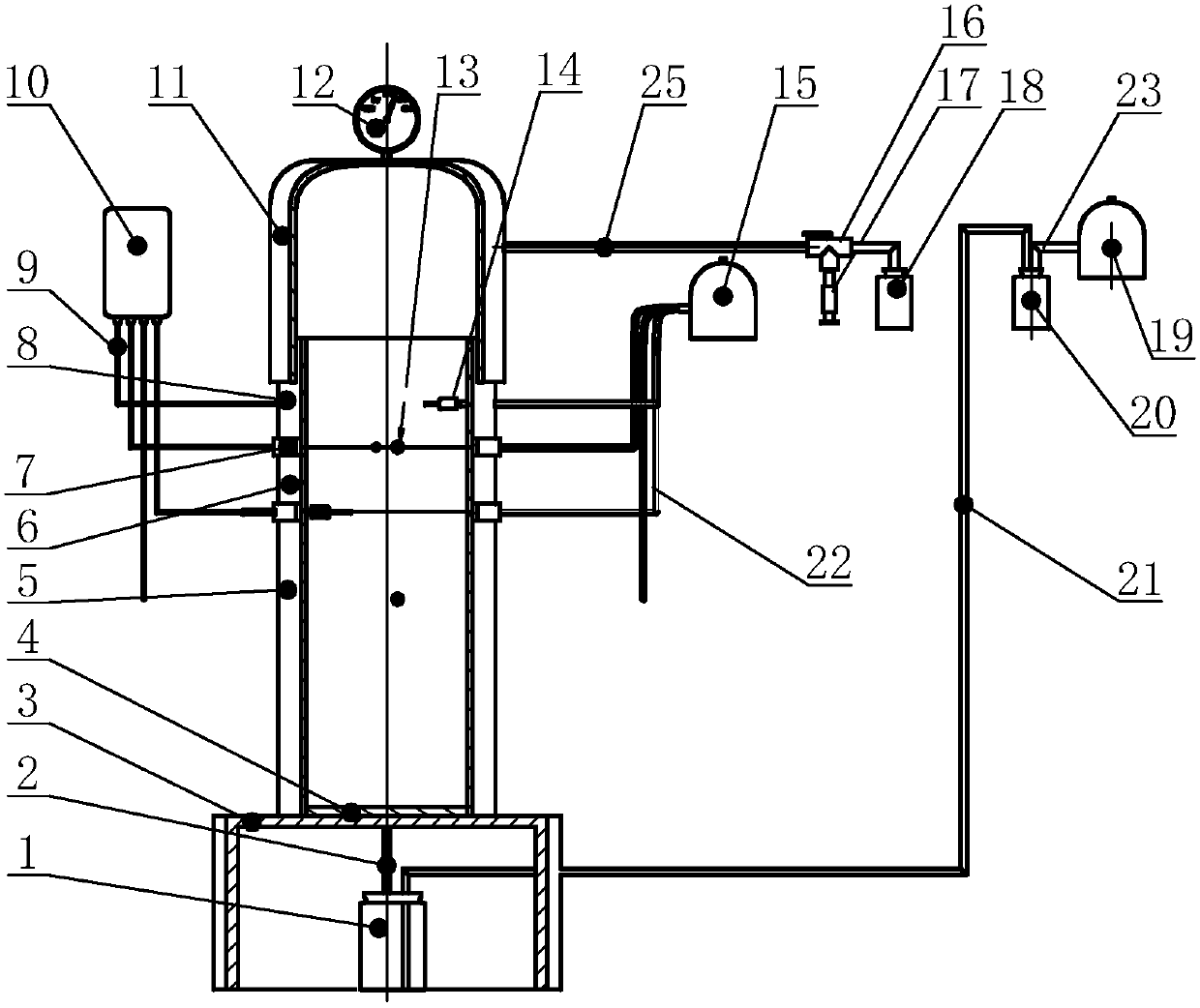
[0027] Example: such as figure 1 Shown, the present invention comprises plexiglass column, base 3, closure cover 11, drench solution extracting device, data collection device 10, soil water collection device 15 and gas sampling device, described base 3 is placed below the plexiglass column, and organic The glass column is placed on the ground together, the top of the plexiglass column is higher than the ground, the base 3 has a built-in liquid collection bottle 1, the liquid collection bottle 1 is connected to the leaching hole at the bottom of the plexiglass column through the conduit I2, and the liquid collection bottle 1 is connected to the leaching solution on the ground The extraction device is connected through the conduit II21, the top of the plexiglass column is provided with a closed cover 11, and the sensing line connected to the data acquisition device 10 and the collection conduit III22 connected to the soil water collection device 15 are respectively arranged at di...


PUM

PropertyMeasurementUnit
heightaaaaaaaaaa
heightaaaaaaaaaa

Abstract

The invention provides a device for simulating soil moisture and fertilizer migration and transformation rules under different plough layer structures and belongs to the technical field of soil monitoring. The device comprises an organic glass column, a base, a seal hood, a leaching solution extraction device, a data acquisition device, a soil moisture acquisition device and a gas sampling device, wherein the base is arranged below the organic glass column; the base and the organic glass column are buried in farmland ambient soil; the top end of the organic glass column is higher than the ground, and the base is internally provided with a liquid collection bottle which is connected with a leaching solution hole in the bottom of the organic glass column by virtue of a guide pipe I; the liquid collection bottle is connected with the leaching solution extraction device by virtue of a guide pipe II; the top end of the organic glass column is provide with the seal hood; the parts, in different heights, of the organic glass columns are respectively provided with a sensing line connected with the data acquisition device and an acquisition guide pipe connected with the soil moisture acquisition device; the seal hood is connected with the sampling device. The device is capable of simulating soil moisture and fertilizer migration and crop growths under different plough layer structures, quantitatively evaluating the advantages and disadvantages of different plough layer structures and providing a basis for reasonable plough layer construction.

Description

technical field [0001] The invention belongs to the technical field of soil monitoring, and in particular relates to an outdoor soil column device for simulating the migration and conversion laws of soil moisture and nutrients and crop growth under different plow layer structures. Background technique [0002] A good tillage layer structure plays an important role in increasing grain production and ensuring national food security. In the late 1970s, with the introduction of foreign rotary tillage equipment and the gradual promotion of rotary tillage, the farming efficiency was greatly improved. Compared with plowing and harrowing, rotary tillage has good soil breaking performance and adaptability. Strong, high operating efficiency advantages. However, the long-term use of rotary tillage has gradually exposed some problems. The current rotary tillage depth is generally about 15cm, which is 8-10cm shallower than the past mechanical plowing depth, resulting in shallower plowin...

Claims


Application Information

Patent Timeline
Patent Type & Authority Patents(China)
IPC IPC(8): G01N33/24
CPCG01N33/24G01N2033/245
Inventor 李玉义逄焕成翟振卢闯魏由庆王婧
Owner INST OF AGRI RESOURCES & REGIONAL PLANNING CHINESE ACADEMY OF AGRI SCI
Learn More