
Total reflection variable focal length short distance projection optics system based on object space telecentricity

A projection optical system, object-side telecentric technology, applied in optics, optical components, instruments, etc., can solve the problems of aberration correction, processing and detection difficulties, difficulty in adapting to diverse environments, and difficulty in correcting chromatic aberration, etc. The effect of adapting to the use environment, broad market application prospects, and reducing processing difficulty

Active Publication Date: 2016-06-29
BEIJING INSTITUTE OF TECHNOLOGYGY
View PDF6 Cites 3 Cited by
  • Summary
  • Abstract
  • Description
  • Claims
  • Application Information

AI Technical Summary

Problems solved by technology

However, the off-axis reflection system composed of four aspheric surfaces in the paper is a fixed-focus system, so the distance between the system and the screen must be limited when using it. There are many restrictions when using it, such as the distance from the screen to the projector and the size of the screen. is fixed, such restrictions will bring a lot of inconvenience to users, making it difficult to adapt to diverse environments; and the design method of using Fresnel mirrors instead of aspheric surfaces will produce chromatic aberration that is difficult to correct, and the structure is complicated; in addition, due to The free-form surface represented by discrete points has difficulties in aberration correction, processing and inspection, and the method of using free-form surfaces instead of aspherical surfaces also has defects.

Method used


Image

  • Total reflection variable focal length short distance projection optics system based on object space telecentricity
  • Total reflection variable focal length short distance projection optics system based on object space telecentricity
  • Total reflection variable focal length short distance projection optics system based on object space telecentricity

Examples


Embodiment Construction

[0020] The present invention will be further described below in conjunction with the accompanying drawings and embodiments.

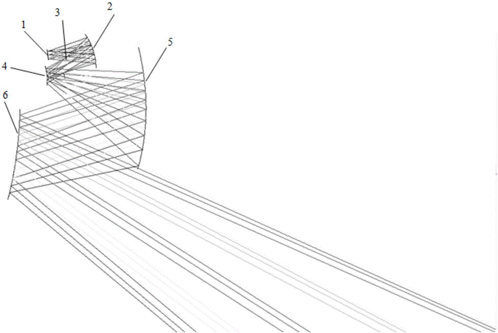
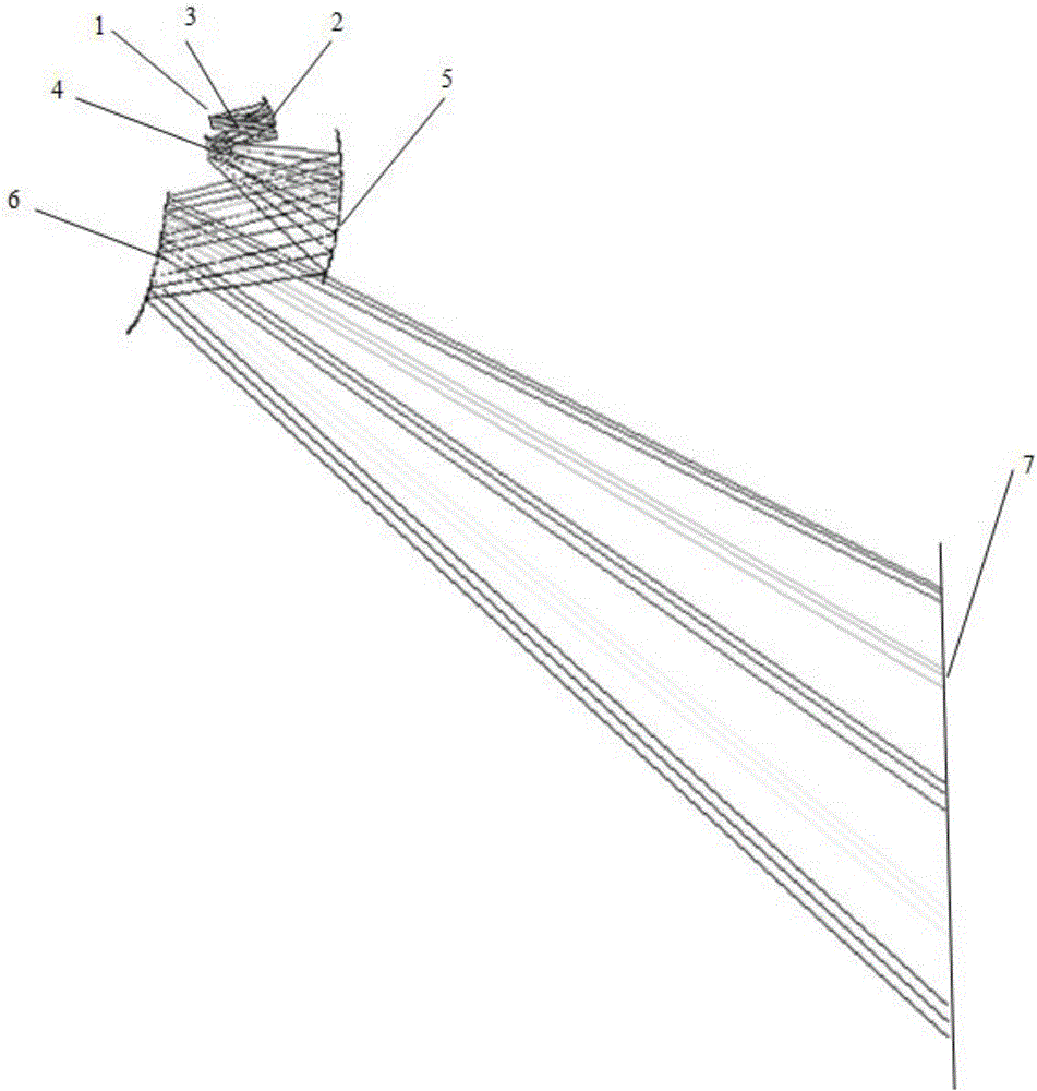
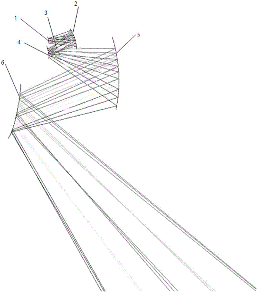
[0021] Example figure 1 As shown, the total reflection zoom short-distance projection optical system based on object space telecentricity of the present invention includes a light-emitting panel (1), a first reflector (2), a diaphragm (3), a second reflector (4), a second Three reflection mirrors (5) and a fourth reflection mirror (6); the above optical elements are placed with a certain eccentricity and off-axis.

[0022] In an embodiment, the image source is generated by a light-emitting panel (the light-emitting panel can be DMD, LCOS, LCD, etc.), firstly reflected by the first reflector. The first reflector is an aspheric reflector, which has certain eccentricity and inclination with respect to the image source, and its main function is to project and enlarge the image source. The light passes through the aperture after passing through the first r...


PUM


Abstract

The invention belongs to the field of optical lens design and particularly relates to a total reflection variable focal length short distance projection optics system based on object space telecentricity.The system comprises a light-emitting panel, a first reflecting mirror, a diaphragm, a second reflecting mirror, a third reflecting mirror and a fourth reflecting mirror.Object space telecentricity is adopted for the system, and subsequent installation and adjustment can be conducted conveniently; the key point lies in that the total reflection type variable focal length optical imaging system design is utilized, good spectrum adaptability is achieved, in addition, the focal length is adjustable, and therefore the system can be adjusted to be adapted to more occasions; short distance projection is achieved by the system, and the system has the advantages that projector distance is short, and the project screen is large.The system meets the requirement of the actual market for commodity adaptability, and the system is small in length, compact in size, low in weight and simple in structure and can be widely applied to the fields such as teaching and culture propaganda.

Description

technical field [0001] The invention belongs to the field of optical lens design, in particular to a total reflection zoom short-distance projection optical system based on object space telecentricity. Background technique [0002] With the development of science and technology and market demand, the short-throw projection optical system has gradually become a hot spot and quickly won the favor of the majority of users. The advantage of the short-throw projection optical system is that it can effectively use the space, realize large-screen projection in a limited space, and will not produce light blocking and glare to the speaker, thereby bringing a more comfortable projection environment. Among them, there is no correction of chromatic aberration in the total reflection projection optical imaging system, which greatly simplifies the structure of the system; multiple reentry of the optical path through the mirror can not only shorten the projection distance, but also reduce ...

Claims


Application Information

Patent Timeline
IPC IPC(8): G02B13/00G02B13/22G02B17/00G02B17/02G02B17/06G03B21/14
CPCG02B13/0065G02B13/22G02B17/008G02B17/023G02B17/06G03B21/142
Inventor 常军杜晓宇陈蔚霖吕凤先刘鑫朱懿沈本兰牛亚军
Owner BEIJING INSTITUTE OF TECHNOLOGYGY
Learn More